IPsec Site-to-Site VPN Example with Pre-Shared Keys
A site-to-site IPsec tunnel interconnects two networks as if they were directly connected by a router. Systems at Site A can reach servers or other systems at Site B, and vice versa. This traffic may also be regulated via firewall rules, as with any other network interface. If more than one client will be connecting to another site from the same controlled location, a site-to-site tunnel will likely be more efficient, not to mention more convenient and easier to maintain.
With a site-to-site tunnel the devices on either local network need not have any knowledge that a VPN exists. No client software is required and all the work is handled by the tunnel endpoints. This is also a good solution for devices that have network connectivity but do not handle VPN connections, such as printers, cameras, HVAC systems, and other embedded hardware.
See also
Site-to-site example configuration
The key to making a working IPsec tunnel is to ensure that both sides have matching settings for authentication, encryption, and so on. Before starting make a note of the local and remote WAN IP addresses as well as the local and remote internal subnets that will be carried across the tunnel. Aside from the cosmetic tunnel Description and these pieces of information the other connection settings will be identical.
The following settings are assumed by this example and some of the subsequent examples in the IPsec recipes:
Site A |
Site B |
||
Name |
Austin Office |
Name |
London Office |
WAN IP |
198.51.100.3 |
WAN IP |
203.0.113.5 |
LAN Subnet |
10.3.0.0/24 |
LAN Subnet |
10.5.0.0/24 |
LAN IP |
10.3.0.1 |
LAN IP |
10.5.0.1 |
Note
To avoid issues with security association duplication, this example uses settings described in Troubleshooting Duplicate IPsec SA Entries.
Figure Site-to-Site IPsec shows the general layout of this VPN.
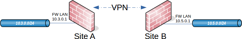
Site-to-Site IPsec
Site A
Start with configuring the tunnel and related settings on the firewall at Site A.
Phase 1
To add a new IPsec phase 1:
Navigate to VPN > IPsec
Click
 Add P1
Fill in the settings as described below
Click Save when complete
Use the following settings for the phase 1 configuration. Many of these settings may be left at their default values unless otherwise noted.
See also
For comprehensive coverage of all IPsec phase 1 settings, see Phase 1 Settings.
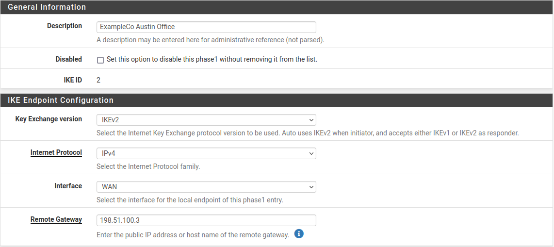
First fill in the top section that holds the general phase 1 information and IKE endpoint configuration, as shown in Figure figure-vpn-tunnel-settings. Items in bold are required. Fill in the settings as described:
- Description:
Text describing the purpose or identity of the tunnel. The best practice is to put the name of Site B in this box, and brief detail about the purpose of the tunnel to help with future administration.
For this example
ExampleCo London Officeis used for the Description to identify where this example tunnel terminates.- Disabled:
Uncheck this box so that the tunnel will be operational.
- Key Exchange version:
Specifies whether to use IKEv2 or IKEv1. IKEv2 is the best practice when both endpoints are compatible. If one side cannot use IKEv2, use IKEv1 instead.
- Internet Protocol:
IPv4 in most cases unless both WANs have IPv6, in which case either type may be used.
- Interface:
Most likely set to WAN, but see the note at Interface Selection on selecting the proper interface when unsure.
- Remote Gateway:
The WAN address at Site B,
203.0.113.5in this example.
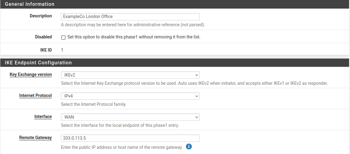
Site A IPsec Phase 1 General Information and IKE Endpoint Configuration
The next section controls IPsec phase 1 proposals for authentication. The defaults are desirable for most of these settings which simplifies the process.
- Authentication Method:
The default, Mutual PSK, is used for this example.
- My Identifier:
The default, My IP Address, is kept for this example.
- Peer Identifier:
The default, Peer IP Address, is kept for this example.
- Pre-Shared Key:
Use a strong key, at least 10 characters in length containing a mix of upper and lowercase letters, numbers and symbols. Enter a custom key or click
 Generate new Pre-Shared Key to automatically populate
the field with a random long string suitable for use as a Pre-Shared Key.
Generate new Pre-Shared Key to automatically populate
the field with a random long string suitable for use as a Pre-Shared Key.Warning
This is the most important setting to get correct. As mentioned in the VPN overview, IPsec using pre-shared keys can be broken if the tunnel uses a weak key.
The exact same key must be entered into the tunnel configuration for Site B later, so note it down or copy and paste it elsewhere. Copy and paste may come in handy, especially with a complex key.
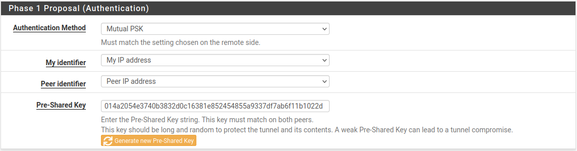
Site A Phase 1 Authentication Settings
The next section controls IPsec phase 1 proposals for encryption.
- Encryption Algorithm:
Use AES with a Key Length of 256 bits.
- Hash Algorithm:
Use SHA256 at a minimum if both sides are compatible, otherwise use the strongest hash available on both endpoints.
- DH Group:
The default of 14 (2048 bit) is OK, higher values are more secure but may use more CPU.
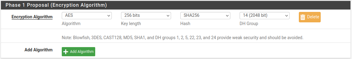
Site A Phase 1 Encryption Settings
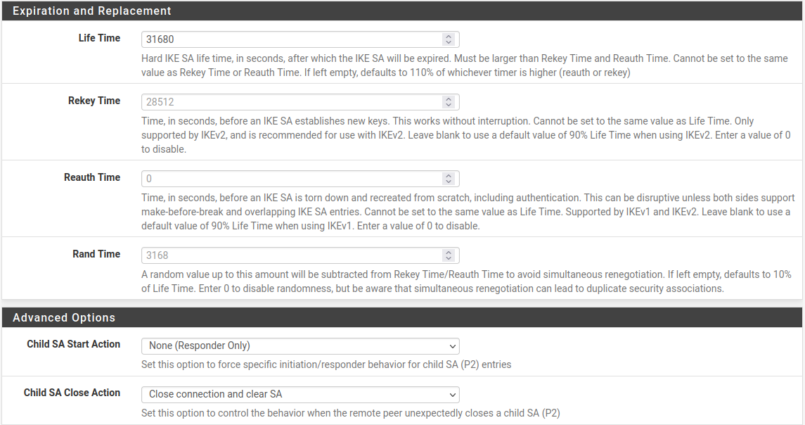
The Expiration and Replacement section controls the timing and method by which the phase 1 will be renegotiated.
- Life Time:
The default
28800is OK for this endpoint.See also
See Troubleshooting Duplicate IPsec SA Entries for best practices in choosing lifetime values.
The other lifetime-related values (Rekey Time, Reauth Time, Rand Time) should be left at their defaults on this endpoint as they are automatically calculated as the correct values.
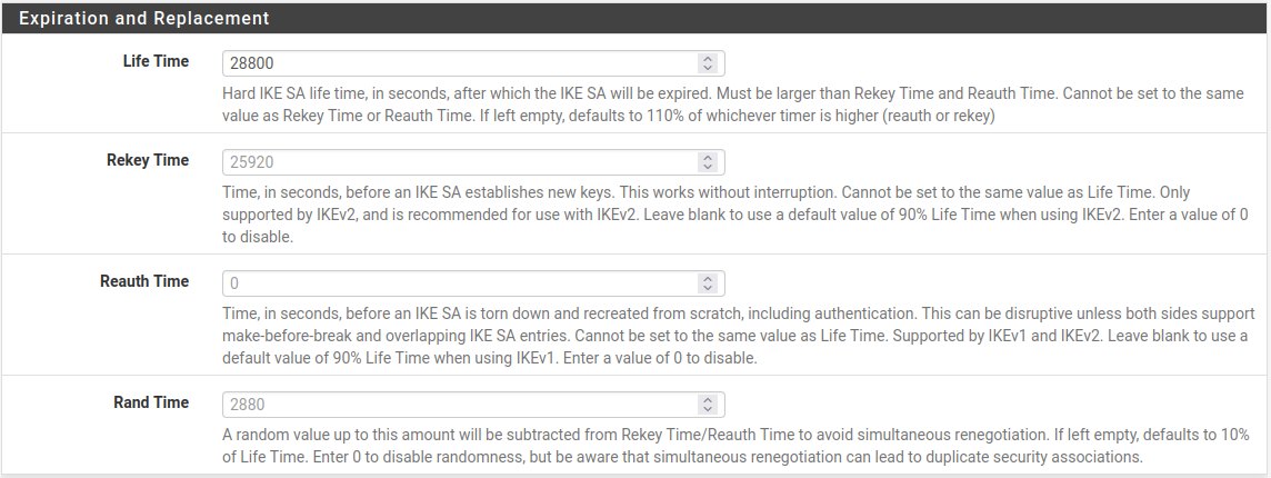
Site A Phase 1 Lifetime Settings
Finally, the Advanced section contains a couple settings to check as well:
- Child SA Close Action:
Set this endpoint to Restart/Reconnect so that the phase 2 entries will be reconnected if they get disconnected.
- Dead Peer Detection:
Leave checked and at the default values.
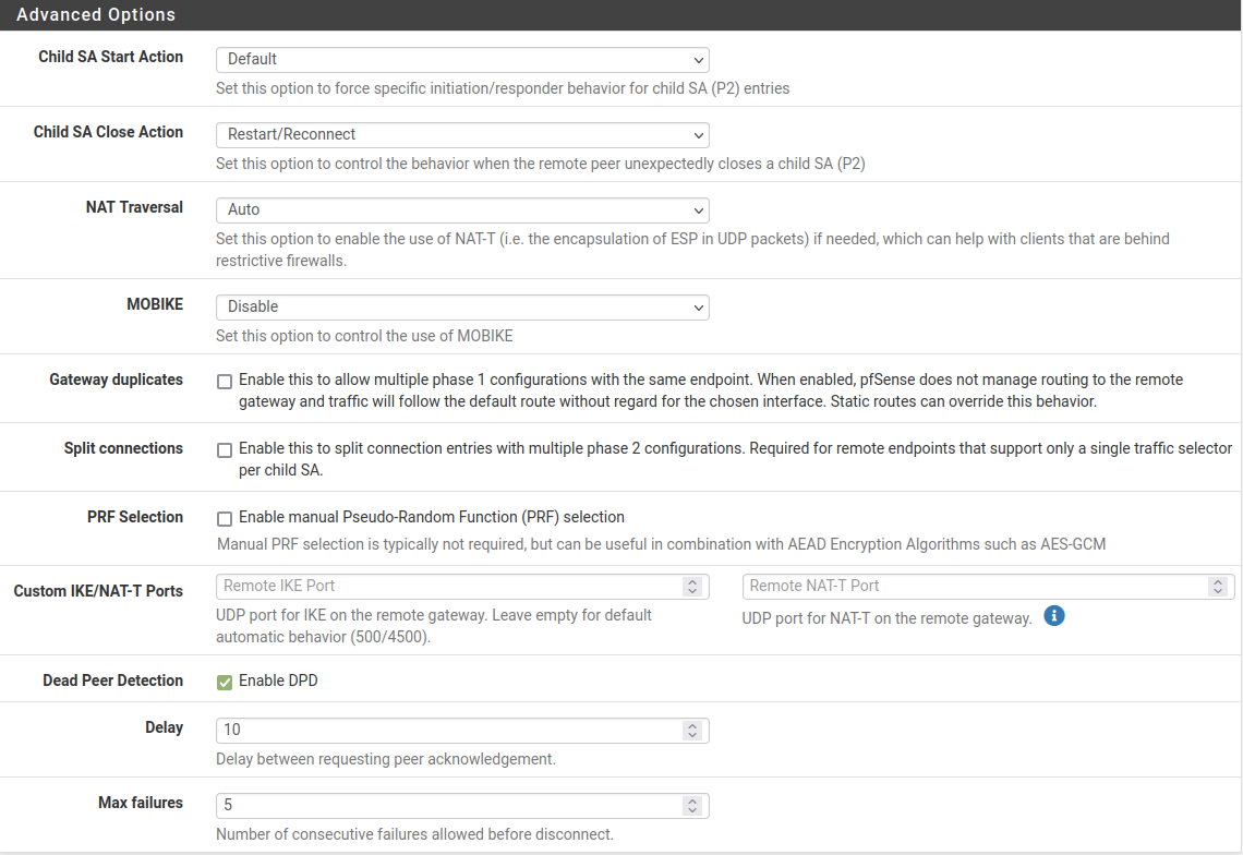
Site A Phase 1 Advanced Settings
Click Save to complete the phase 1 setup.
Phase 2
With the phase 1 entry complete, now a new phase 2 definition to the VPN:
Click
 Show Phase 2 Entries as seen in Figure
Site A Phase 2 List (Empty) to expand the phase 2 list for this
VPN.
Show Phase 2 Entries as seen in Figure
Site A Phase 2 List (Empty) to expand the phase 2 list for this
VPN.Click
Add P2 to add a new phase 2 entry, as seen in
Figure Adding a Phase 2 entry to Site A.
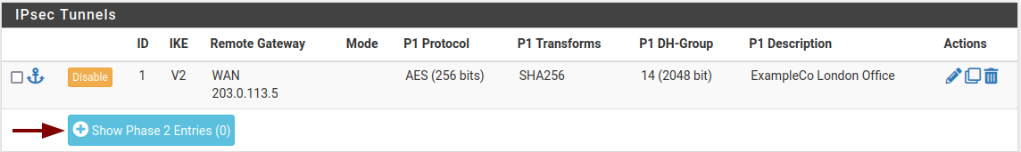
Site A Phase 2 List (Empty)
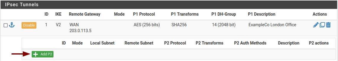
Adding a Phase 2 entry to Site A
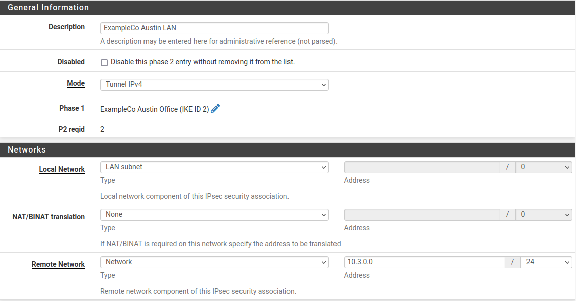
Now add settings for phase 2 on this VPN. The settings for phase 2 (Figure Site A Phase 2 General Information and Networks) can vary more than phase 1.
See also
For comprehensive coverage of all IPsec phase 2 settings, see Phase 2 Settings.
- Description:
A brief description of the network(s) involved in this phase 2 entry.
- Mode:
Since this example is for a policy-based tunnel, select Tunnel IPv4
- Local Network:
In most cases the best practice is to leave this as LAN Subnet, but it can be changed to Network with the proper subnet value filled in. In this case that would be
10.3.0.0/24. Leaving it as LAN Subnet will ensure that if the network is renumbered in the future, this end of the tunnel will follow. If that does happen, the other end must be changed manually.- NAT/BINAT:
Set to None.
- Remote Network:
Set to the network at Site B, in this case
10.5.0.0/24.

Site A Phase 2 General Information and Networks
The next section of the phase 2 settings covers traffic encryption. Encryption algorithms and Hash algorithms can both be set to allow multiple options in phase 2, and both sides will negotiate and agree upon the settings so long as each side has at least one of each in common. In some cases that may be a good thing, but it is usually better to restrict this to the single specific options desired on both sides.
- Protocol:
Set to ESP for encryption.
- Encryption algorithm:
The best practice is to use an AEAD cipher such as AES-GCM if it is compatible with both endpoints.
Select AES256-GCM with a 128-bit key length. Otherwise, use AES 256, or the highest strength cipher available on both endpoints.
- Hash algorithm:
If AES-GCM is selected for Encryption Algorithm do not select any hashes.
Otherwise, use SHA256 or the strongest hash available on both endpoints.
- PFS:
Perfect Forward Secrecy (PFS) is optional but can help protect against certain key attacks. This example uses 14 (2048 bit).
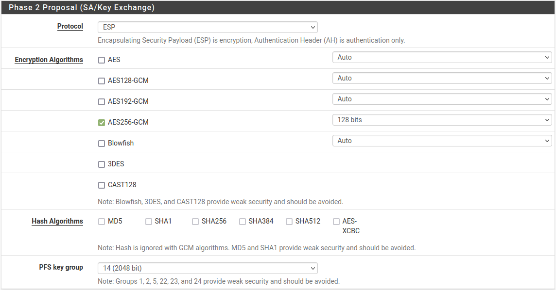
Site A Phase 2 Proposal Settings
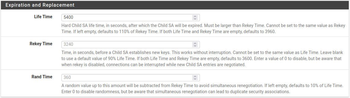
Next are the settings which govern timing and methods for renewing phase 2 keys.
- Life Time:
Use
3600for this example, and leave Rekey Time and Rand Time at their default calculated placeholder values.

Site A Phase 2 Expiration and Replacement Settings
To finalize the settings and put them into action:
Click Save
Click Apply Changes on the IPsec Tunnels screen, as seen in Figure Apply IPsec Settings.

Apply IPsec Settings
The tunnel configuration for Site A is now complete.
Firewall Rules
Firewall rules are necessary to allow traffic from the network at Site B to enter through the IPsec tunnel.
Navigate to Firewall > Rules on the IPsec tab and add rules there to pass traffic from the remote side of the VPN.
See also
See Firewall for specifics on adding rules, and IPsec and firewall rules for firewall rule advice specific to IPsec.
Rules may be as permissive or restrictive as desired. For example, they can allow any protocol from anywhere to anywhere or only allow TCP from a certain host on Site B to a certain host at Site A on a certain port.
As with other firewall rules the connections are checked on the way into the firewall; the source of all traffic on the IPsec tab rules will be remote VPN networks, such as those at Site B.
Make sure the source addresses on the firewall rules match Site B addresses,
such as 10.5.0.0/24. The destination addresses will be on Site A, such as
10.3.0.0/24.
Site B
Now that Site A is configured, it is time to tackle Site B. Repeat the process on the Site B endpoint to add a tunnel.
Only a few parts of this setup will differ from Site A as shown in Figure Site B Phase 1 General Settings and Figure Site B Phase 2 General Settings:
The phase 1 settings for Description, WAN address, Life Time, Child SA Start Action, and Child SA Close Action
The phase 2 tunnel networks and Life Time
Add a phase 1 entry to the Site B firewall using similar settings to Site A, but with the following differences:
- Description:
ExampleCo Austin Office.- Remote Gateway:
The WAN address at Site A,
198.51.100.3.- Life Time:
At least 10% higher than Site A,
31680- Child SA Start Action:
Set to None (Responder Only) so that this endpoint will not initiate on its own, but will wait for Site A to initiate.
- Child SA Close Action:
Set this endpoint to Close Connection and clear SA so that the phase 2 will not automatically reconnect, since Site A will be managing that.
Click Save
Add a phase 2 entry to the Site B firewall using similar settings to Site A, but with the following differences:
- Description:
ExampleCo Austin LAN.- Remote Subnet:
The network at Site A, in this case
10.3.0.0/24.- Life Time:
At least 10% higher than Site A,
5400
Site B Phase 1 General Settings
Site B Phase 1 Other Settings
Site B Phase 2 General Settings
Site B Phase 2 Lifetime Settings
Click Save
Click Apply changes on the IPsec Tunnels screen.
As with Site A, firewall rules must also be added to allow traffic on the tunnel to cross from Site A to Site B. Add these rules to the IPsec tab under Firewall > Rules. For more details, see IPsec and firewall rules. This time, the source of the traffic would be Site A, destination Site B.
Check Status
Both tunnels are now configured and active. Check the IPsec status by visiting Status > IPsec. A description of the tunnel is shown along with its status.
If the tunnel is not listed as Established, there may be a problem establishing the tunnel. At this point in time, the most likely reason is that no traffic has yet attempted to cross the tunnel.
A connect button is offered on this screen that will attempt to initiate the
tunnel. Click the  Connect VPN button to attempt to
bring up the tunnel as seen in Figure Site A IPsec Status.
Connect VPN button to attempt to
bring up the tunnel as seen in Figure Site A IPsec Status.

Site A IPsec Status
If the connect button does not appear, try sending an ICMP ping to a system in the remote subnet at Site B from a device inside the phase 2 local network at Site A (or vice versa) to see if the tunnel establishes. Look at Testing IPsec Connectivity for other means of testing a tunnel.
Failing that, the IPsec logs will typically offer an explanation. They are located under Status > System Logs on the IPsec tab. Be sure to check the status and logs at both sites. For more troubleshooting information, check the Troubleshooting IPsec VPNs section later in this chapter.
When the tunnel is connected the status will look like Figure Site A IPsec Status while Connected.
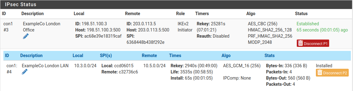
Site A IPsec Status while Connected