WireGuard Site-to-Multisite VPN Configuration Example
This recipe explains how to set up a VPN tunnel between three firewalls in a site-to-multisite configuration using WireGuard.
This example is a minimal configuration, more complicated scenarios are possible, see WireGuard for details.
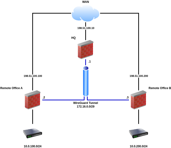
WireGuard Example Site-to-Multisite Network
Required Information
General Values
Item |
Value |
|---|---|
Design |
Site-to-Multisite, one peer per tunnel (spokes), multiple peers per tunnel (hubs) |
Tunnel Subnet |
|
HQ:
Item |
Value |
|---|---|
WAN IP Address |
|
Tunnel Address |
|
Listen Port |
|
Remote Office A:
Item |
Value |
|---|---|
WAN IP Address |
|
Tunnel Address |
|
Listen Port |
|
LAN Subnet |
|
Remote Office B:
Item |
Value |
|---|---|
WAN IP Address |
|
Tunnel Address |
|
Listen Port |
|
LAN Subnet |
|
WireGuard Configuration
Navigate to VPN > WireGuard > Settings
Fill in the following options:
- Enable:
Checked
- Interface Group Membership:
Only Unassigned Tunnels
Click
 Save
Save
Tip
When allowing inbound connections from arbitrary remote networks, use rules only on assigned WireGuard interface tabs only to ensure proper return routing.
Note
Rules on assigned WireGuard interface tabs get reply-to which ensures
that traffic entering a specific assigned WireGuard interface exits back out
the same interface. Without that, return traffic will follow the default
gateway.
Tunnel Configuration
First, create the WireGuard tunnel on all three sites:
Navigate to VPN > WireGuard > Tunnels
Click
 Add Tunnel
Fill in the options using the information determined earlier, with variations noted for each site:
- Enabled:
Checked
- HQ Settings:
- Description:
Remote Sites VPN
- Remote Office A Settings:
- Description:
HQ VPN
- Remote Office B Settings:
- Description:
HQ VPN
- Listen Port:
51820- Interface Keys:
Click Generate to create a new set of keys.
Copy the public key from each firewall and note which is which
Click
Save Tunnel
Peer Configuration
The peer entry for the server can be added when editing the tunnel. Follow these steps on both sites, with the differences in settings noted inline.
Edit the tunnel:
Navigate to VPN > WireGuard > Tunnels
Locate the WireGuard tunnel for this VPN
Click
 at the end of the row for the tunnel
From the tunnel editing page, add a peer:
Click
Add PeerFill in the options using the information determined earlier, with variations noted for each site:
- HQ Settings:
- Description:
Remote Office A Peer- Dynamic Endpoint:
Unchecked
- Endpoint:
198.51.100.100(the WAN IP address of Remote Site A)- Endpoint Port:
51820- Public Key:
The public key from the Remote Office A firewall
- Allowed IPs:
172.16.0.2/32and10.0.100.0/24(Remote Site A Tunnel Interface and LAN)
- HQ Settings:
- Description:
Remote Office B Peer- Dynamic Endpoint:
Unchecked
- Endpoint:
198.51.100.200(the WAN IP address of Remote Site B)- Endpoint Port:
51820- Public Key:
The public key from the Remote Office B firewall
- Allowed IPs:
172.16.0.3/32and10.0.200.0/24(Remote Site B Tunnel Interface and LAN)
- Remote Office A Settings:
- Description:
HQ Peer- Dynamic Endpoint:
Unchecked
- Endpoint:
198.51.100.10(the WAN IP address of HQ)- Endpoint Port:
51820- Public Key:
The public key from the HQ firewall
- Allowed IPs:
172.16.0.0/29and10.0.200.0/24(Tunnel Network and Remote Site B LAN)
- Remote Office B Settings:
- Description:
HQ Peer- Dynamic Endpoint:
Unchecked
- Endpoint:
198.51.100.10(the WAN IP address of HQ)- Endpoint Port:
51820- Public Key:
The public key from the HQ firewall
- Allowed IPs:
172.16.0.0/29and10.0.100.0/24(Tunnel Network and Remote Site A LAN)
Click
Save Peer
Assign Interface
These steps should be done on all sites.
First, fix the default gateway so WireGuard isn’t automatically selected before it’s ready:
Navigate to System > Routing
Set Default Gateway IPv4 to a specific gateway (e.g. WANGW) or group
Set Default Gateway IPv6 similarly if this VPN will also carry IPv6 traffic
Click
SaveClick
 Apply Changes
Next, assign the interface (Assign a WireGuard Interface):
Navigate to Interfaces > Assignments
Select the appropriate
tun_wg<number>interface in the Available network ports listClick
Add to assign the interface as a new OPT interface (e.g.
OPT1)Navigate to the Interface configuration page, Interfaces > OPTx
Check Enable
Enter an appropriate Description which will become the interface name (e.g.
VPN_HQ,VPN_SITEA, orVPN_SITEB)Configure an appropriate MTU value for the WireGuard interface (e.g.
1420for IPv4+IPv6 or1440for IPv4 only).For details on calculating the correct MTU, see in Assign a WireGuard Interface.
Fill in the options using the information determined earlier, with variations noted for each site:
- HQ Settings (VPN_HQ):
- IPv4 Configuration Type:
Static IPV4- IPv4 Address:
172.16.0.1/29
- Remote Office A Settings (VPN_SITEA):
- IPv4 Configuration Type:
Static IPV4- IPv4 Address:
172.16.0.2/29
- Remote Office B Settings (VPN_SITEB):
- IPv4 Configuration Type:
Static IPV4- IPv4 Address:
172.16.0.3/29
Click
SaveClick
Apply Changes
Firewall Rules
First, add a rule to the WAN on both firewalls to allow traffic to reach WireGuard:
Note
Traffic flowing between peers is subject to firewall rules on the associated WireGuard interface.
Navigate to Firewall > Rules, WAN tab
Click
 Add to create a new firewall rule at the top of the
list so that it matches before other rules
Add to create a new firewall rule at the top of the
list so that it matches before other rulesConfigure the firewall rule as follows:
- Action:
Pass
- Protocol:
UDP
- Source:
This can typically be left at Any, but it is more secure to fill in the IP address of the opposing firewall.
- Destination:
WAN Address
- Destination Port Range:
(other),
51820- Description:
Pass traffic to WireGuard
Click
SaveClick
Apply Changes
Next, add a rule to pass traffic inside the WireGuard tunnel on both firewalls:
Navigate to Firewall > Rules
Click the tab for the assigned WireGuard interface (e.g. VPN_HQ, VPN_SITEA, or VPN_SITEB)
Click
Add to add a new rule to the top of the listUse the following settings:
- Action:
Pass
- Protocol:
Any
- Source:
any
- Destination:
any
- Description:
Pass VPN traffic from WireGuard peers
Note
This rule allows all traffic between sites, which is easy but not a secure practice. Traffic between the sites can be restricted as needed with less permissive rules.
Click
SaveClick
Apply Changes
Routing
These steps should be performed on all sites:
Navigate to System > Routing > Gateways
Click
AddFill in the options using the information determined earlier, with variations noted for each site:
- HQ Settings:
- Interface:
tun_wg<number>- Address Family:
IPv4- Name:
WG_SITEA_GW4- Gateway:
172.16.0.2
- HQ Settings:
- Interface:
tun_wg<number>- Address Family:
IPv4- Name:
WG_SITEB_GW4- Gateway:
172.16.0.3
- Remote Office A/B:
- Interface:
tun_wg<number>- Address Family:
IPv4- Name:
WG_HQ_GW4- Gateway:
172.16.0.1
Click
SaveClick
Apply Changes
Specific networks can be routed across the VPN by adding a static route for the network(s) under System > Routing on the Static Routes tab.
These steps should be done on all sites.
Navigate to System > Routing > Static Routes
Click
AddFill in the options using the information determined earlier, with variations noted for each site:
- HQ Settings:
- Destination Network:
10.0.100.0/24(e.g. Remote Office A LAN segment)- Gateway:
WG_SITEA_GW4
- HQ Settings:
- Destination Network:
10.0.200.0/24(e.g. Remote Office B LAN segment)- Gateway:
WG_SITEB_GW4
- Remote Office A Settings:
- Destination Network:
10.0.200.0/24(e.g. Remote Office B LAN segment)- Gateway:
WG_HQ_GW4
- Remote Office B Settings:
- Destination Network:
10.0.100.0/24(e.g. Remote Office A LAN segment)- Gateway:
WG_HQ_GW4
Click
SaveClick
Apply Changes
See also
As an alternative to static routing in this way, dynamic routing protocols can also work with WireGuard. See WireGuard Routing for more information.
Tip
These gateways can also be used for policy routing if needed.
Finish Up
The configuration is now complete! The two remote office sites should now have full LAN-to-LAN connectivity via HQ.