Configuring Switches with VLANs
This section provides guidance on configuring a few varieties of switches for use with VLANs. This offers generic guidance that will apply to most if not all 802.1Q capable switches, then goes on to cover configuration on specific switches from Cisco, HP, Netgear, and Dell.
Note
This is the bare minimum configuration needed for VLANs to function, and it does not necessarily show the ideal secure switch configuration for any specific environment. An in depth discussion of switch security is outside the scope of this documentation.
Switch configuration overview
Generally three or four things must be configured on VLAN capable switches:
Add/define the VLANs
Most switches have a means of defining a list of configured VLANs, and they must be added before they can be configured on any ports.
Configure the trunk port
The port to which the firewall running pfSense® software will be connected must be configured as a trunk port, tagging all possible VLANs on the interface.
Configure the access ports
Configure ports for internal hosts as access ports on the desired VLANs, with untagged VLANs.
Configure the Port VLAN ID (PVID)
Some switches require configuring the PVID for access ports. This specifies which VLAN to use for the traffic entering that switch port. For some switches this is a one-step process, by configuring the port as an access port on a particular VLAN, it automatically tags traffic coming in on that port. Other switches require this to be configured in one or two places. Check the switch documentation for details if it is not one detailed in this chapter.
Cisco IOS based switches
Configuring and using VLANs on Cisco switches with IOS is a fairly simple process, taking only a few commands to create and use VLANs, trunk ports, and assigning ports to VLANs. Many switches from other vendors behave similarly to IOS, and will use nearly the same if not identical syntax for configuration.
Create VLANs
VLANs can be created in a standalone fashion, or using VLAN Trunk Protocol (VTP). Using VTP may be more convenient, as it will automatically propagate the VLAN configuration to all switches on a VTP domain, though it also can create its own security problems and open up possibilities for inadvertently wiping out the VLAN configuration.
With VTP, to add another VLAN it only needs to be configured on a single switch, and then all other trunked switches in the group can assign ports to that VLAN. If VLANs are configured independently, they must be added to each switch by hand. Refer to Cisco’s documentation on VTP to ensure a secure configuration use used, and that it is not prone to accidental destruction.
In a network with only a few switches where VLANs do not change frequently, VTP may be overkill and avoiding it will also avoid its potential downfalls.
Standalone VLANs
To create standalone VLANs:
sw# vlan database
sw(vlan)# vlan 10 name "DMZ Servers"
sw(vlan)# vlan 20 name "Phones"
sw(vlan)# exit
VTP VLANs
To set up a switch for VTP and VLANs, create a VTP database on the master switch and then create two VLANs:
sw# vlan database
sw(vlan)# vtp server
sw(vlan)# vtp domain example.com
sw(vlan)# vtp password SuperSecret
sw(vlan)# vlan 10 name "DMZ Servers"
sw(vlan)# vlan 20 name "Phones"
sw(vlan)# exit
Configure Trunk Port
For handing off VLANs to pfSense software a switch port not only has to be in trunk mode, but also must be using 802.1q tagging. This can be done like so:
sw# configure terminal
sw(config)# interface FastEthernet 0/24
sw(config-if)# switchport mode trunk
sw(config-if)# switchport trunk encapsulation dot1q
Note
On some newer Cisco IOS switches, the Cisco-proprietary ISL VLAN
encapsulation method is deprecated. If a switch does not allow the
encapsulation dot1q configuration option, it can only use 802.1Q and the
encapsulation does not need to be specified.
Add Ports to the VLAN
To add ports to these VLANs, assign them as follows:
sw# configure terminal
sw(config)# interface FastEthernet 0/12
sw(config-if)# switchport mode access
sw(config-if)# switchport access vlan 10
Cisco CatOS based switches
Creating VLANs on CatOS is a little different, though the terminology is the same as using VLANs under IOS. Standalone VLANs and VTP are both possible to maintain the VLAN database:
# set vtp domain example mode server
# set vtp passwd SuperSecret
# set vlan 10 name dmz
# set vlan 20 name phones
Then configure a trunk port to automatically handle every VLAN:
# set trunk 5/24 on dot1q 1-4094
Then add ports to the VLAN:
# set vlan 10 5/1-8
# set vlan 20 5/9-15
HP ProCurve switches
HP ProCurve switches only implement 802.1q trunking, so no configuration is needed for encapsulation. First, ssh or telnet into the switch and bring up the management menu.
Enable VLAN Support
First, VLAN support needs to be enabled on the switch if it is not already:
Choose Switch configuration
Choose Advanced Features
Choose VLAN Menu…
Choose VLAN Support
Set Enable VLANs to Yes if it is not already, and choose a number of VLANs. Each time this value is changed the switch must be restarted, so ensure it is large enough to contain as many VLANs as necessary.
Restart the switch to apply the changes.
Create VLANs
Before the VLANs can be assigned to ports, The VLANs must be created. At the switch configuration menu:
Choose Switch configuration
Choose Advanced Features
Choose VLAN Menu…
Choose VLAN Names
Choose Add
Enter the VLAN ID,
10Enter the name,
DMZChoose Save
Repeat the steps from Add to Save for any remaining VLANs
Assigning Trunk Ports to VLANs
Next, configure the trunk port for the firewall as well as any trunk ports going to other switches containing multiple VLANs.
Choose Switch configuration
Choose VLAN Menu…
Choose VLAN Port Assignment
Choose Edit
Find the port to assign
Press space on Default VLAN until it shows No
Move over to the column for each of the VLANs on this trunk port, and Press space until it shows Tagged. Every VLAN in use must be tagged on the trunk port.
Assigning Access Ports to VLANs
Choose Switch configuration
Choose VLAN Menu…
Choose VLAN Port Assignment
Choose Edit
Find the port to assign
Press space on Default VLAN until it shows No
Move over to the column for the VLAN to which this port will be assigned
Press space until it shows Untagged.
Netgear Managed Switches
This example is on a GS108Tv1, but other Netgear models are all very similar if not identical. There are also several other vendors including Zyxel who sell switches made by the same manufacturer, using the same web interface with a different logo. Log into the web interface of the switch to start.
Planning the VLAN configuration
Before configuring the switch, several items are required:
The number of VLANs to be configured
The IDs to use for the VLANs
How each switch port needs to be configured
For this example, an 8 port GS108Tv1 is used, and it will be configured as shown in Table Netgear GS108T VLAN Configuration.
Switch port |
VLAN mode |
VLAN assigned |
|---|---|---|
1 |
trunk |
10 and 20, tagged |
2 |
access |
10 untagged |
3 |
access |
10 untagged |
4 |
access |
10 untagged |
5 |
access |
20 untagged |
6 |
access |
20 untagged |
7 |
access |
20 untagged |
8 |
access |
20 untagged |
Enable 802.1Q VLANs
To configure the switch to use 802.1Q VLAN trunking:
Navigate to the System menu on the left side of the page
Click VLAN Group Setting, as indicated in Figure VLAN Group Setting.

VLAN Group Setting
Select IEEE 802.1Q VLAN (Figure Enable 802.1Q VLANs).

Enable 802.1Q VLANs
Click OK to confirm the switch to 802.1Q trunking, as shown in Figure Confirm change to 802.1Q VLAN.
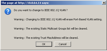
Confirm change to 802.1Q VLAN
After clicking OK, the page will refresh with the 802.1Q VLAN configuration as shown in Figure Default 802.1Q Configuration.
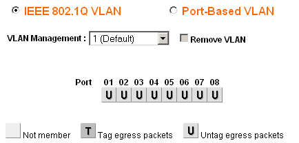
Default 802.1Q Configuration
Add VLANs
For this example, two VLANs are added with IDs 10 and 20.
To add a VLAN:
Click the VLAN Management select box
Click Add New VLAN as shown in Figure Add New VLAN.
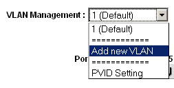
Add New VLAN
Enter the VLAN ID for this new VLAN, such as
10Click Apply. The VLAN screen is now ready to configure VLAN 10 (Figure Add VLAN 10).
Click Add New VLAN again as shown in Figure Add New VLAN to add VLAN 20 (Figure Add VLAN 20).
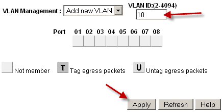
Add VLAN 10
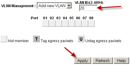
Add VLAN 20
Add as many VLANs as needed, then continue to the next section.
Configure VLAN tagging
When a VLAN is selected from the VLAN Management select box, it shows how that VLAN is configured on each port:
A blank box means the port is not a member of the selected VLAN.
A box containing T means the VLAN is sent on that port with the 802.1Q tag.
U indicates the port is a member of that VLAN and it leaves the port untagged.
The trunk port must have both VLANs added and tagged.
Warning
Do not change the configuration of the port being used to access the web interface of the switch! This will lock the administrator out of the switch. The only means of recovery on the GS108Tv2 is using the reset to factory defaults button since it does not have a serial console. For the switches that have serial consoles, keep a null modem cable handy in case network connectivity with the switch is lost. Configuring the management VLAN is covered later in this section.
Click in the boxes beneath the port number as shown in Figure ref:figure-toggle-vlan-membership to toggle between the three VLAN options.
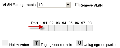
Toggle VLAN Membership
Configure VLAN 10 membership
Figure Configure VLAN 10 Membership shows VLAN 10 configured as outlined in Table table-netgear-gs108t-vlan-configuration. The access ports on this VLAN are set to untagged while the trunk port is set to tagged.
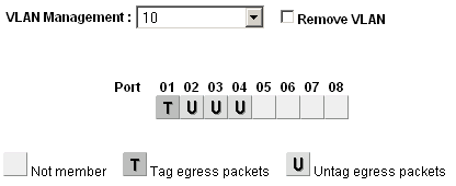
Configure VLAN 10 Membership
Configure VLAN 20 membership
Select 20 from the VLAN Management select box to configure the port memberships for VLAN 20.
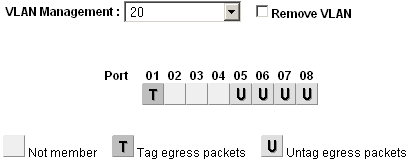
Configure VLAN 20 Membership
Change PVID
On Netgear switches, in addition to the previously configured tagging settings, the PVID must also be configured to specify the VLAN used for frames entering a port:
Select PVID from the VLAN Management select box as shown in Figure PVID Setting.
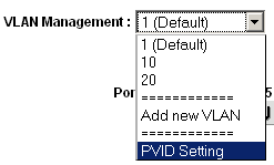
PVID Setting
The default PVID setting is VLAN 1 for all ports as shown in Figure Default PVID Configuration.

Default PVID Configuration
Change the PVID for each access port, but leave the trunk port and port used to access the switch management interface set to
1.Figure VLAN 10 and 20 PVID Configuration shows the PVID configuration matching the port assignments shown in Table Netgear GS108T VLAN Configuration, with port 8 being used to access the switch management interface.

VLAN 10 and 20 PVID Configuration
Apply changes when finished
Remove VLAN 1 configuration
By default, all ports are members of VLAN 1 with untagged egress frames. To remove VLAN 1 from the other ports:
Select 1 (Default) from the VLAN Management select box
Remove VLAN 1 from all ports except the one used to manage the switch and the trunk port, to avoid being disconnected.
In this example, port 8 is used to manage the switch. When finished, the screen will look like Figure Remove VLAN 1 Membership.

Remove VLAN 1 Membership
Apply changes when finished
Verify VLAN functionality
Configure VLANs on pfSense, including the DHCP server on the VLAN interfaces if needed. Plug systems into the configured access ports and test connectivity. If everything works as desired, continue to the next step. If things do not work as intended, review the tagging and PVID configuration on the switch, and the VLAN configuration and interface assignments on pfSense software.
Dell PowerConnect managed switches
The management interface of Dell switches varies slightly between models, but the following procedure will accommodate most models. The configuration is quite similar in style to Cisco IOS.
First, create the VLANs:
console# config
console(config)# vlan database
console(config-vlan)# vlan 10 name dmz media ethernet
console(config-vlan)# vlan 20 name phones media ethernet
console(config-vlan)# exit
Next, set up a trunk port:
console(config)# interface ethernet 1/1
console(config-if)# switchport mode trunk
console(config-if)# switchport allowed vlan add 1-4094 tagged
console(config-if)# exit
Finally, add ports to the VLANs:
console(config)# interface ethernet 1/15
console(config-if)# switchport allowed vlan add 10 untagged
console(config-if)# exit