Configuring a High Availability Cluster
Note
The WAN and LAN must be configured with static addresses. See High Availability Prerequisites for IP address details.
This is the heart of the process, which will link the devices and allow them to function together.
Setup Sync Interface
Before proceeding, the Sync interfaces on the cluster nodes must be configured. Sync Interface IP Address Assignments lists the addresses to use for the Sync interfaces on each node.
Navigate to Interfaces and choose the interface to use on the SYNC port
Check Enable Interface
Enter
SYNCfor the DescriptionSet IPv4 Configuration Type to Static IPv4
Set IPv4 address to
172.16.1.2when configuring the primary node, or172.16.1.3when configuring the secondary nodeSelect 24 for the subnet mask in the CIDR drop-down next to IPv4 address
Do not check Block private networks or Block bogon networks
Click Save
Click Apply Changes
Once that procedure has been completed on the primary node, perform it again on the secondary node with the appropriate IPv4 address value.
After configuring the sync interface, the interface assignments list, Interfaces menu, firewall rules, and other locations should all have an entry labeled SYNC.
Add Firewall Rules for Synchronization
To complete the Sync interface configuration, firewall rules must be added to both nodes to allow synchronization.
At a minimum, the firewall rules must pass configuration synchronization traffic
(by default, HTTPS on port TCP 443), pfsync traffic, and Kea DHCP HA traffic
on TCP ports 8765 and 8766. In most cases, a simple “allow all” style
rule is sufficient, but using specific rules is a better practice.
This guide shows both methods, and it will also serve as an indicator that synchronization is working.
On the primary node:
Set up a rule to allow configuration synchronization:
Navigate to Firewall > Rules on the SYNC tab
Click
 at the top of the list to create a new rule
Configure the rule as follows:
- Action:
Pass
- Protocol:
TCP
- Source:
SYNC Subnets
- Destination:
SYNC Address
- Destination port range:
443or choose HTTPS (443) from the drop-down selector- Description:
Allow configuration synchronization
Click Save
Set up a rule to allow state synchronization:
Click
 at the top of the list to create another new rule
Configure the rule as follows:
- Action:
Pass
- Protocol:
pfsync
- Source:
SYNC Subnets
- Destination:
any
- Description:
Allow state synchronization
Click Save
Set up a rule to allow ICMP for diagnostics, e.g. echo (ping) requests:
Click
at the top of the list to create another new ruleConfigure the rule as follows:
- Action:
Pass
- Protocol:
ICMP
- Source:
SYNC Subnets
- Destination:
SYNC Subnets
- Description:
Allow ICMP for diagnostics
Click Save
Set up a rule to allow DHCP high availability traffic:
Navigate to Firewall > Rules on the SYNC tab
Click
at the top of the list to create a new ruleConfigure the rule as follows:
- Action:
Pass
- Address Family:
IPv4+IPv6
- Protocol:
TCP
- Source:
SYNC Subnets
- Destination:
SYNC Address
- Destination port range:
8756to8766- Description:
Allow DHCP Sync
Click Save
Click Apply Changes
When complete, the rules will look like the following:
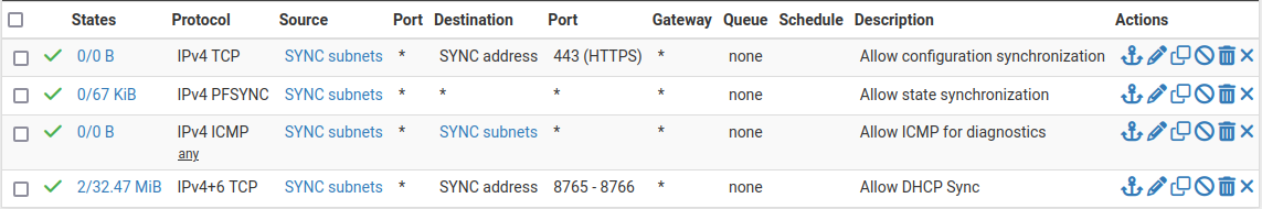
Example Sync Interface Firewall Rules
On the secondary node:
Navigate to Firewall > Rules on the SYNC tab
Click
at the top of the list to create a new ruleConfigure the rule as follows:
- Action:
Pass
- Protocol:
any
- Source:
SYNC Subnets
- Destination:
any
- Description:
Temp rule for sync
Click Save
Click Apply Changes
Note
The rule on the secondary is different, but that is intended at this point. Once the first configuration synchronization has taken place, the temporary rule on the secondary will be replaced by the rules from the primary. Seeing that the rules changed on the Sync interface is a good indicator that it worked!
Configure pfsync
State synchronization using pfsync must be configured on both the primary and secondary nodes to function.
First on the primary node and then on the secondary, perform the following:
Navigate to System > High Availability
Check Synchronize States
Set Synchronize Interface to SYNC
Set a custom Filter Host ID
For example,
1on the primary node,2on the secondary node.Set pfsync Synchronize Peer IP to the Sync interface IPv4 address of the other node
Set this to
172.16.1.3on the primary node, or172.16.1.2on the secondary nodeClick Save
Configure XMLRPC
Warning
Configuration synchronization must only be configured on the primary node. Never activate options in this section on the secondary node of a two-member cluster.
On the primary node only, perform the following:
Navigate to System > High Availability
Set Synchronize Config to IP to the Sync interface IP address of the secondary node:
172.16.1.3Set Remote System Username to
admin.Note
This must either be the
adminaccount or a user on both nodes with the “System - HA node sync” privilege.Set Remote System Password to the admin user account password, and repeat the value in the confirmation box.
Check the boxes for each area to synchronize to the secondary node.
For this guide, as with most configurations, all boxes are checked.
Tip
Use the Toggle All button to select all the options at once, rather than selecting them individually.
Click Save
As a quick confirmation that the synchronization worked, on the secondary node navigate to Firewall > Rules, SYNC tab. The rules entered on the primary should now be present on the tab, and the temporary rule has been removed.
The two nodes are now linked for configuration synchronization! Compatible areas will synchronize to the secondary node whenever a change is made on the primary node.
Warning
Do not make changes to the secondary in areas set to be synchronized! These changes will be overwritten the next time the primary node performs a synchronization.
Note
If certificates are included in XMLRPC synchronization, the primary node will synchronize its GUI certificate to the secondary. After that has synchronized, it must be manually selected on the secondary node under System > Advanced on the Admin Access tab. Otherwise, the secondary may regenerate a new certificate any time the GUI starts as its expected entry is missing. Alternately, import the GUI certificate for the secondary on the primary so they are both present on both nodes, then select it for use on the secondary again after it synchronizes.
Add CARP VIPs
With configuration synchronization in place, the CARP Virtual IP addresses need only be added to the primary node, and they will automatically copy to the secondary node.
This guide uses multiple CARP VIPs for WAN and LAN to accommodate IPv4 and IPv6. See CARP VIP VHID Assignments for a list of CARP VIPs and VHID values for this example setup.
Navigate to Firewall > Virtual IPs on the primary node to manage CARP VIPs
Click
 Add at the top of the list to create a new VIP.
Note
Each interface handling user traffic must have a CARP VIP, in this case WAN and LAN.
Fill in the VIP options as described below. See CARP VIP VHID Assignments for specific settings unique to each VIP in this example.
- Type:
CARP
- Interface:
The interface upon which the VIP resides, e.g. WAN
- Address(es):
The IP address and subnet mask/prefix value for the VIP. Consult CARP VIP VHID Assignments for the address values in this example.
Note
The subnet mask/prefix must match the subnet mask on the interface IP addresses. For example, the first VIP
198.51.100.200and24on WAN (See WAN Interface IP Address Assignments).- Virtual IP Password:
Password for the CARP VIP. Use a random value.
This need only match between the two nodes, which will be handled by synchronization. The password and confirm password box must both be filled in and they must match.
- VHID Group:
Virtual ID for the CARP VIP. Consult CARP VIP VHID Assignments for the VHID to use for each address in this example. See Determine CARP VHID Availability for information on finding available VHID values for a network.
Tip
A common tactic is to make the VHID match the last octet of the IP address, e.g.
200for an address ending in.200.- Advertising Frequency:
How often the node sends CARP heartbeats on its interface.
- Base:
Whole seconds between Heartbeats, typically 1.
- Skew:
Fractions of a second (1/256th increments).
Note
A primary node is typically set to 0 or 1, secondary nodes will be 100 or higher. This adjustment is handled automatically by XMLRPC synchronization.
- Description:
Text to identify the VIP, such as
WAN CARP VIP.
Click Save when finished, then repeat that process for each additional VIP. If there are any additional IP addresses in the WAN subnet that will be used for purposes such as 1:1 NAT, port forwards, VPNs, etc., add them now.
Tip
For HA setups designed with multiple CARP VIPs of the same address family on the same interface, instead consider adding the additional CARP VIPs as IP alias VIPs which use a single CARP VIP as their parent interface. This reduces the number of CARP VIP heartbeats on a network segment and also allows the VIPs to fail as a group.
After creating entries for all VIPs on the cluster, click Apply Changes.
Check Firewall > Virtual IPs on the secondary node to ensure that the VIPs synchronized as expected.
The Virtual IP addresses on both nodes will look like the following if the process was successful.
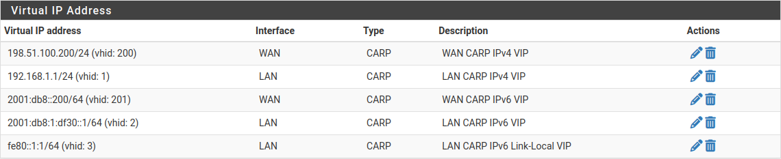
CARP Virtual IP Address List
Check CARP and State Synchronization Status
Now visit Status > CARP on both nodes to confirm the proper status.
The primary node should indicate MASTER status for all VIPs, and the secondary node should indicate BACKUP status for all VIPs.
The State Synchronization Status area should show the chosen Filter Host ID for each node if the states have synchronized successfully.
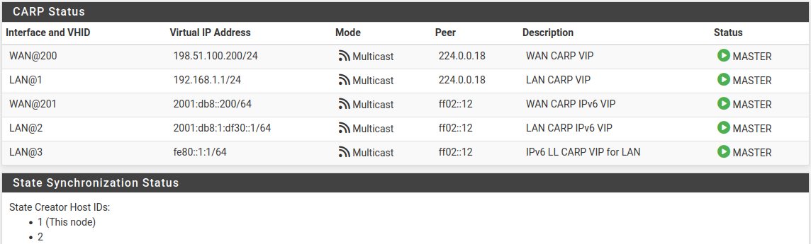
CARP VIP Status and State Synchronization Status on Primary
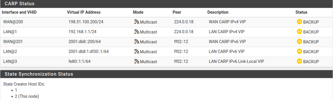
CARP VIP Status and State Synchronization Status on Secondary
If the status is incorrect, see Troubleshooting High Availability.
Setup Outbound NAT
Now it is time to put the new CARP VIPs to use. The Outbound NAT settings will synchronize, so these changes need only be made to the primary node.
Navigate to Firewall > NAT, Outbound tab
Click to select Hybrid Outbound NAT rule generation
Click Save
Hybrid mode allows the default NAT rules to stay in place, but also allows the default rules to be overridden by manually created rules. This way it becomes unnecessary to manage entries for the firewall itself (which should not use the CARP VIP for NAT) and it can also make the process less disruptive when adding new interfaces later.
Create outbound NAT rules for internal subnet sources to work with the CARP IP address.
Click
below the Mappings section to add a new ruleConfigure the rule as follows:
- Interface:
WAN
- Address Family:
IPv4
- Source:
LAN Subnets
- Translation, Address:
Choose the WAN CARP IPv4 VIP from the Address drop-down, 198.51.100.200
- Description:
LAN to WAN
Leave all other options at the default values.
Click Save
Click
below the Mappings section to add another new rule to
the top of the list for IPsec pass-through.Note
This is optional and may be omitted if there will not be any LAN clients connecting to external IPsec servers which lack NAT-T capabilities.
Configure the rule as follows:
- Interface:
WAN
- Address Family:
IPv4
- Source:
LAN Subnets
- Destination:
- Type:
Any
- Port:
500
- Translation:
- Address:
Choose the WAN CARP IPv4 VIP from the Address drop-down, 198.51.100.200
- Port or Range:
Check Static Port
- Description:
ISAKMP - LAN to WAN
Leave all other options at the default values.
Click Save
Click Apply Changes
Warning
If an additional local interface is added later, such as a second LAN, DMZ, etc., and that interface uses private IP addresses, then additional outbound NAT rules must be added to translate those sources. Similarly, if additional WANs are added later, they will also need a set of outbound NAT rules.
Danger
Do not use an overly permissive source on outbound NAT rules! If an outbound NAT rule matches traffic from the firewall using a VIP, it can break several protocols and cause instability. Use only local/internal networks as the source on NAT rules, or an alias containing those local private networks.
Any rules using Localhost as a source must use an interface address for translation and not a CARP VIP.
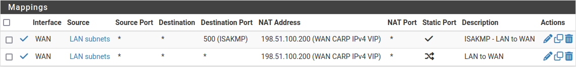
Outbound NAT Rules for LAN with CARP VIP
Other NAT Concerns
If there are any port forwards to be added using the WAN CARP VIP, they may be added now using Firewall > NAT, Port Forward tab. Port forwards will work the same as usual, but the Destination will be the WAN CARP VIP.
Set up the DHCP Server
The DHCP server daemons on the cluster nodes need adjustments so that they can work together. The changes will synchronize from the primary to the secondary, so as with the VIPs and Outbound NAT, these changes need only be made on the primary node.
Note
This guide assumes the Kea DHCP Backend is active as it is the only backend capable of HA operation for both IPv4 and IPv6.
Set the Backend
On both nodes, ensure the Kea DHCP backend is active:
Navigate to System > Advanced, Networking tab
Set the Server Backend to Kea DHCP in the DHCP Options section if it is not already selected
Click Save if the value was changed
Configure DHCP for IPv4
On the primary node only, enable HA for IPv4 DHCP in the Kea Settings:
Navigate to Services > DHCP Server, Settings tab
Check Enable high availability
Set Node Role to Primary
Set Local Name to a custom value, e.g.
ha-primarySet Local Address to the IP address of the sync interface on the primary node, e.g.
172.16.1.2Set Remote Name to the name of the secondary node, e.g.
ha-secondary.Set Remote Address to the IP address of the Sync interface on the secondary node, e.g.
172.16.1.3Configure TLS Transport to encrypt the DHCP HA traffic (optional)
The Sync interface is directly connected in this example, so there is no risk of the traffic being intercepted, but using encryption is still a best practice. Note that TLS settings do not synchronize and must be configured separately on each node.
Click Save
Note
XMLRPC configuration synchronization will adjust these options appropriately when copying the settings to the secondary node.
Still on the primary node only, configure the LAN interface DHCP settings to use the LAN CARP IPv4 VIP:
Navigate to Services > DHCP Server, LAN* tab.
Set the DNS Server to the LAN CARP VIP, here
192.168.1.1Set the Gateway to the LAN CARP VIP, here
192.168.1.1Click Save
Setting the DNS Server and Gateway to a CARP VIP ensures that the local clients are talking to the failover address and not directly to either node. This way if the primary fails, the local clients will continue talking to the secondary node.
Configure DHCP for IPv6
Configure DHCPv6 HA
On the primary node only, enable HA for IPv6 DHCP in the Kea Settings:
Navigate to Services > DHCPv6 Server, Settings tab
Check Enable high availability
Set Node Role to Primary
Set Local Name to a custom value, e.g.
ha-primarySet Local Address to the IP address of the sync interface on the primary node, e.g.
2001:db8:1:df31::2Set Remote Name to the name of the secondary node, e.g.
ha-secondary.Set Remote Address to the IP address of the Sync interface on the secondary node, e.g.
2001:db8:1:df31::3Configure TLS Transport to encrypt the DHCP HA traffic (optional)
The Sync interface is directly connected in this example, so there is no risk of the traffic being intercepted, but using encryption is still a best practice. Note that TLS settings do not synchronize and must be configured separately on each node.
Click Save
Note
XMLRPC configuration synchronization will adjust these options appropriately when copying the settings to the secondary node.
Configure DHCPv6 Interface Settings
Still on the primary node only, configure the LAN interface DHCPv6 settings to use the LAN IPv6 CARP VIP for DNS.
Navigate to Services > DHCPv6 Server, LAN tab
Set the DNS Server to the LAN CARP VIP, here
2001:db8:1:df30::1Click Save
Configure IPv6 Router Advertisements
Finally, configure IPv6 Router Advertisements (RA) to use the LAN CARP IPv6 Link-Local VIP for the IPv6 gateway:
Navigate to Services > Router Advertisement, LAN tab
Set Router Mode to Managed so that clients will use DHCPv6 to obtain addresses and other settings.
Set RA Interface to the LAN CARP IPv6 Link-Local VIP, fe80::1:1
Check Enable DNS
Check Mirror DHCPv6 to have the RA daemon advertise the same DNS settings as the DHCPv6 server
Click Save
Check DHCP High Availability Status
On both nodes, visit Status > DHCP Leases and Status > DHCPv6 Leases to see the status. There is a High Availability section at the bottom of the page which contains the HA status. When the two nodes are working properly, both nodes will indicate a “hot-standby” state.
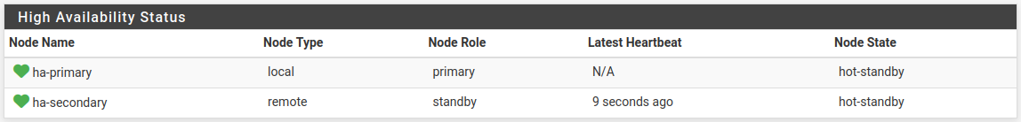
Kea DHCP High Availability Status
VPNs and Other Services
When configuring a VPN, such as OpenVPN or IPsec, pick a WAN CARP VIP as the Interface for the VPN and ensure the remote peer also builds the other side of the tunnel using the CARP VIP as the peer address.
For other local services, packages, etc. likewise a CARP VIP is recommended for binding if the service will work on both nodes.
High Availability capability in packages varies. Check the package documentation for information on if, or how, various aspects of High Availability work with a specific package.
Additional Interfaces
Additional local interfaces may also be configured, repeating some of the previous steps as needed:
Assign the interface on both nodes identically
Enable the interface on both nodes, using different IP addresses within the same subnet
Add a CARP VIP inside the new subnet (Primary node only)
Add firewall rules (Primary node only)
Add Outbound NAT rules for a source of the new subnet, utilizing the CARP VIP for translation (Primary node only)
Configure the DHCP server for the new subnet, utilizing the CARP VIP for DNS and Gateway roles (Optional, Primary node only)