M.2 NVMe SSD Installation
The Netgate® 4200 has built-in onboard eMMC storage. Optionally, a PCIe-based M.2 NVMe drive can be installed as an upgrade or to bypass the onboard eMMC flash memory.
Warnings and Precautions
Danger
Anti-static protection must be used throughout this procedure.
Warning
pfSense® Plus software must be wiped from the onboard eMMC storage before reinstalling pfSense Plus software on the M.2 NVMe SSD. This is covered later within the installation procedure in this document.
For more details on why this is necessary and how to wipe the disk, see https://docs.netgate.com/pfsense/en/latest/troubleshooting/multiple-disks.html
Warning
The Netgate 4200 is only compatible PCIe-based M.2 NVMe storage devices. It is not compatible with M.2 SATA devices.
The Netgate 4200 has one socket compatible with a PCIe-based M.2 NVMe drive: Socket #3 labeled J13. This is the rear socket nearest to the I/O panel. This is an M-Key socket which accepts M.2 B+M-Key or M-Key PCIe NVMe SSDs only.
See M.2 Socket Specifications and Capabilities for more information.
Danger
Take all appropriate precautions and exercise care when handling the exposed system board and M.2 card. There are many delicate components which can be damaged during this process. Damage caused via physical contact and electrostatic discharge while performing this installation is not covered by the warranty.
Required Tools and Hardware
Installing an M.2 NVMe SSD in the Netgate 4200 requires the following tools and hardware:
#1 Phillips screwdriver
T10 Torx driver
Anti-static grounding strap and anti-static mat for handling bare M.2 card and 4200 system
1 x PCIe-based M.2 NVMe SSD, 2280 size, B+M-key or M-key card
1 x M2.5-0.45 x 6mm Phillips pan head machine screw
See also
This guide assumes a 2280 size card. Other cards may work, but require additional hardware for installation. See the following FAQ topics for details:
Installation Procedure
The installation procedure has many steps which are broken down into related groups in the remainder of this document. Follow all steps in the procedure carefully.
Take a Backup
If the system contains an existing configuration which should be carried over to the SSD, then the first step is to take a backup of that configuration.
If the existing configuration is not necessary, this section may be skipped.
There are numerous backup options covered in the pfSense software documentation section on Backup and Restore.
For the purposes of reinstalling and restoring, the easiest method is to take a local backup.
Download the Installer
Before proceeding further, download a copy of the Netgate Installer amd64 memstick image using a Netgate Store Account and write the installer to a USB memstick. For details, see Reinstalling pfSense Plus Software.
Wipe the eMMC
To ensure the old installation of pfSense software on the eMMC does not interfere with the new installation of pfSense software on the SSD, the metadata on the eMMC must be wiped.
Warning
Do not skip this procedure. Failing to wipe the eMMC may result in installation failures, upgrade failures, or other unpredictable behavior from having two conflicting installations present.
Boot the Netgate Installer
Choose the option to start a Rescue Shell when prompted
Follow the rest of the procedure for wiping the disks in the pfSense software documentation at https://docs.netgate.com/pfsense/en/latest/troubleshooting/multiple-disks.html
Note
The eMMC storage device will appear as da1 in most cases when booting
the installer via USB. When following the procedure to wipe the disks, use
that device and not da0 which is likely the installer memstick in the
rescue shell.
To confirm the correct device, run the command geom disk list from the
rescue shell. One device description will include Ultra HS-COMBO and that
device is the eMMC storage.
After wiping the eMMC, run the command shutdown -p now from the rescue shell
to cleanly shut down and power off the device.
Power Off and Disconnect
Installing the SSD requires removing the top of the case to expose the internal components. Before opening the case, the Netgate 4200 must be completely disconnected from everything. This includes power, network cables, USB cables, serial console cables, and any other cable or devices connected to the Netgate 4200.
Danger
Reminder:
Anti-static protection must be used throughout this procedure.
Any hardware damage incurred during this procedure is not covered by the hardware warranty.
Unplug the power cable
Danger
Wait at least 60 seconds after unplugging power to proceed. This ensures that all phantom power has dissipated.
Unplug all network cables, USB cables and devices, serial console connections, etc.
Dismount the Netgate 4200 device if it is secured in some way (e.g. wall mount)
Move the Netgate 4200 to a safe work location such as an anti-static mat
Removing the Lid
The next portion of the procedure involves opening the device and removing the lid.
Danger
Reminder:
Anti-static protection must be used throughout this procedure.
Any hardware damage incurred during this procedure is not covered by the hardware warranty.
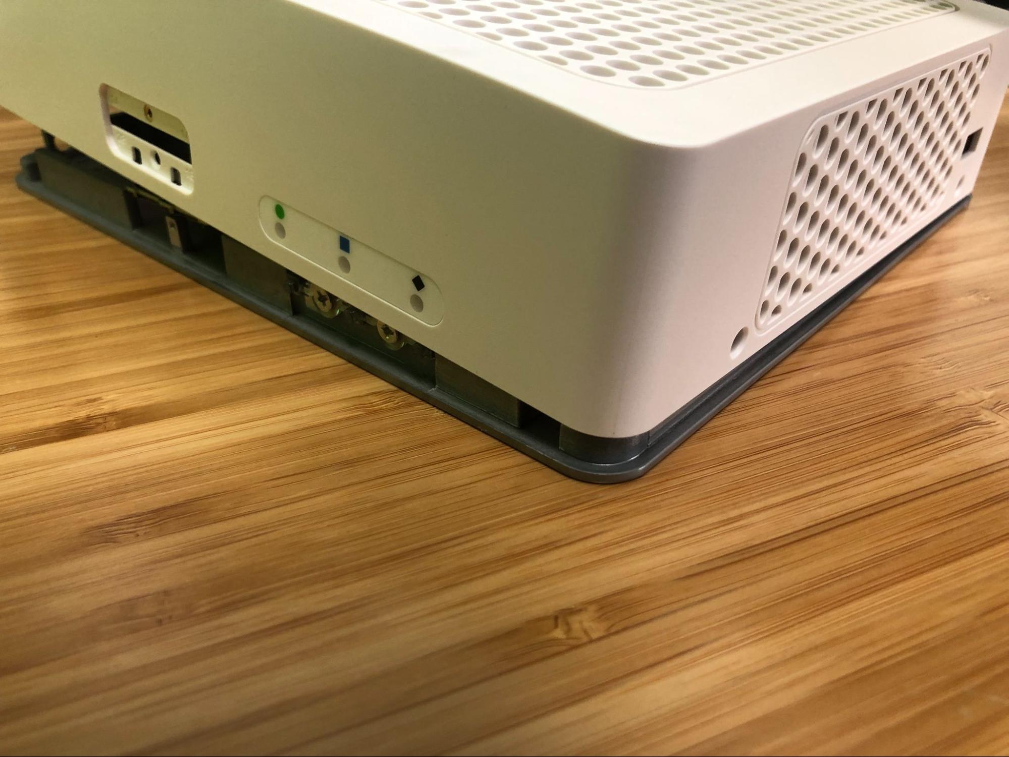
Remove the SIM card slot cover screw using the #1 Phillips head screwdriver.
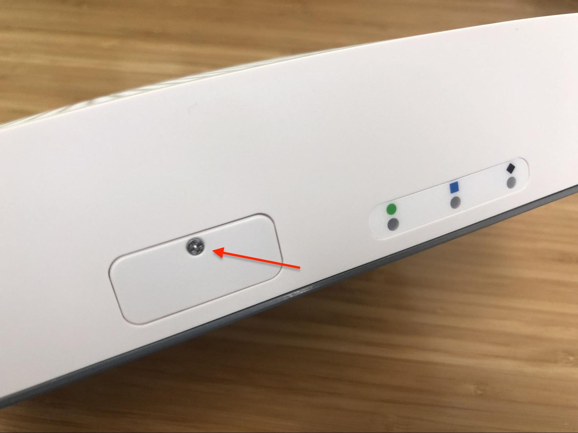
SIM card slot cover screw location
Remove the SIM card slot cover.
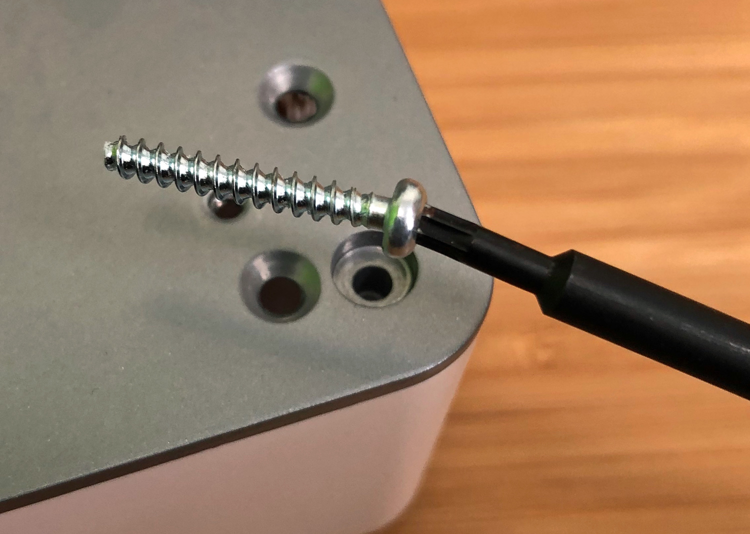
Remove the SIM card slot retention screw using the #1 Phillips head screwdriver.
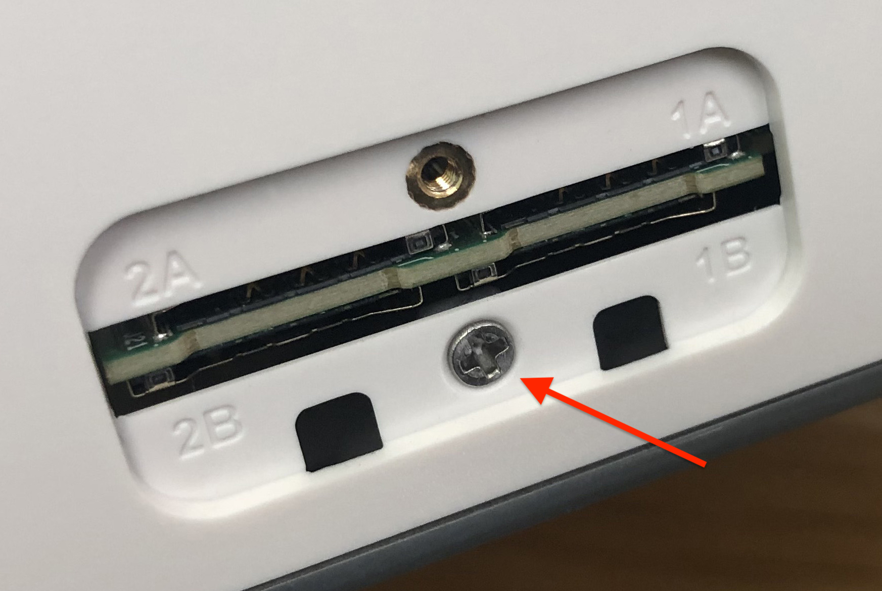
SIM card slot retention screw location
Turn the device over carefully and protect the surface to avoid damaging the vented lid of the device
Tip
An anti-static mat or similar non-marring work surface is ideal for this role.
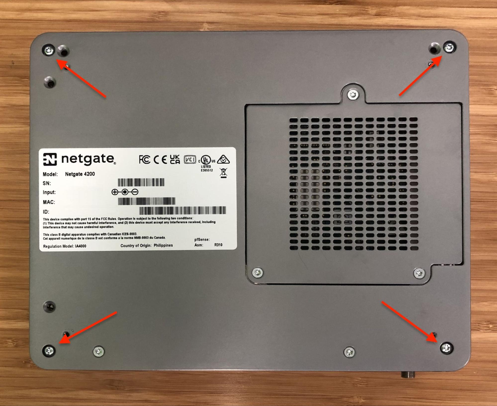
Locate the four (4) T10 Torx pan head machine screws holding the plastic and rubber feet onto the chassis
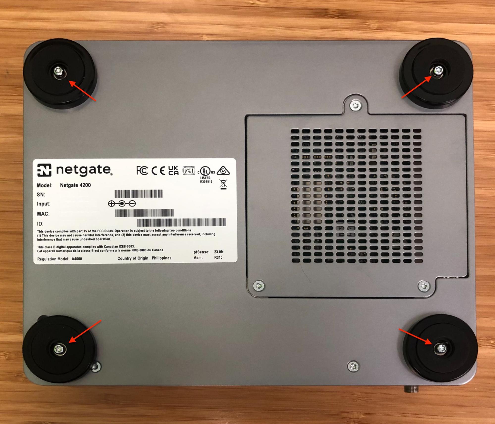
Foot screw locations
Remove the four (4) T10 Torx pan head machine screws and washers holding the plastic and rubber feet using a T10 Torx driver.
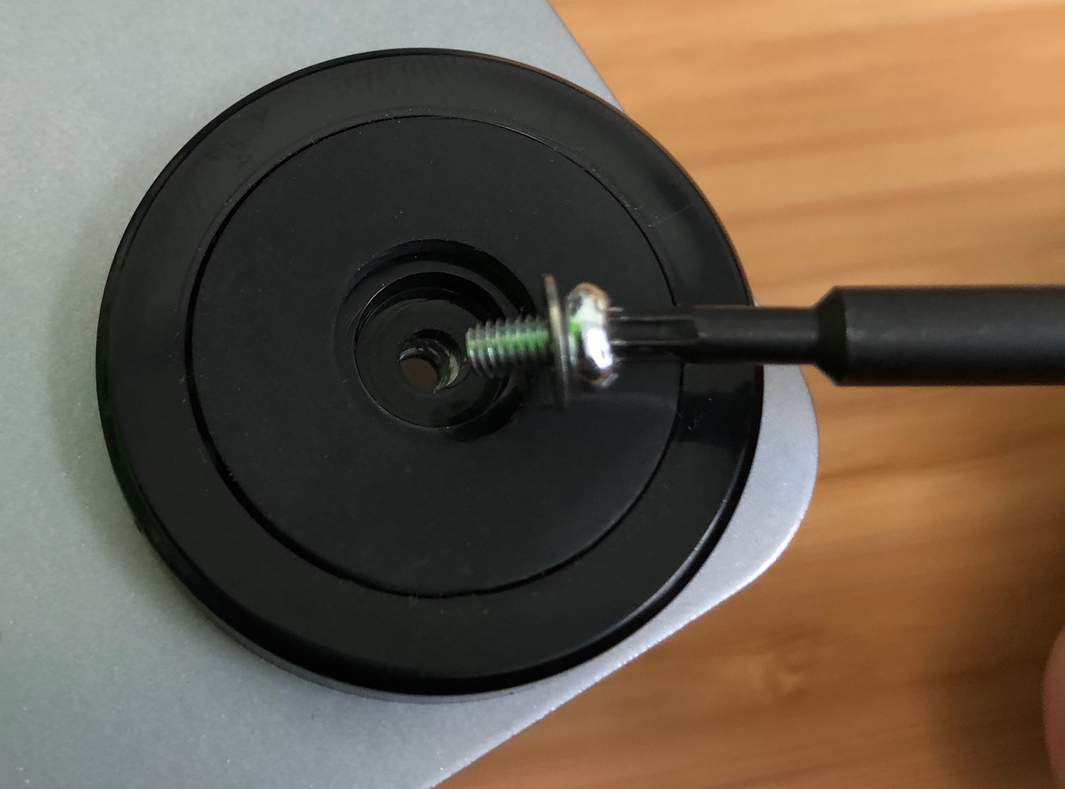
Foot screw and washer removal
Remove the four (4) plastic and rubber feet.
Remove the four (4) long T10 Torx plas-tite threaded screws from the chassis corners using the T10 Torx driver.
Plas-tite chassis screw removal
Turn the device so the I/O panel (“rear” of the system) is visible.
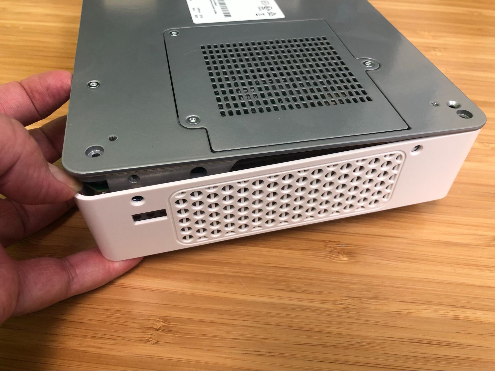
Using fingers, gently pry the edge of the plastic lid away from the I/O panel, starting from either corner of the device.
Lid removal starting at a corner
Continue gently prying the corner while starting to pull the metal base and I/O panel up and away from the lid.
Separating the lid from the metal base
Continue separating the lid from the chassis, gradually work around to the front of the lid where the LEDs and SIM slots are located.
Tip
At this point it may be easier to tilt the device upright on its side.
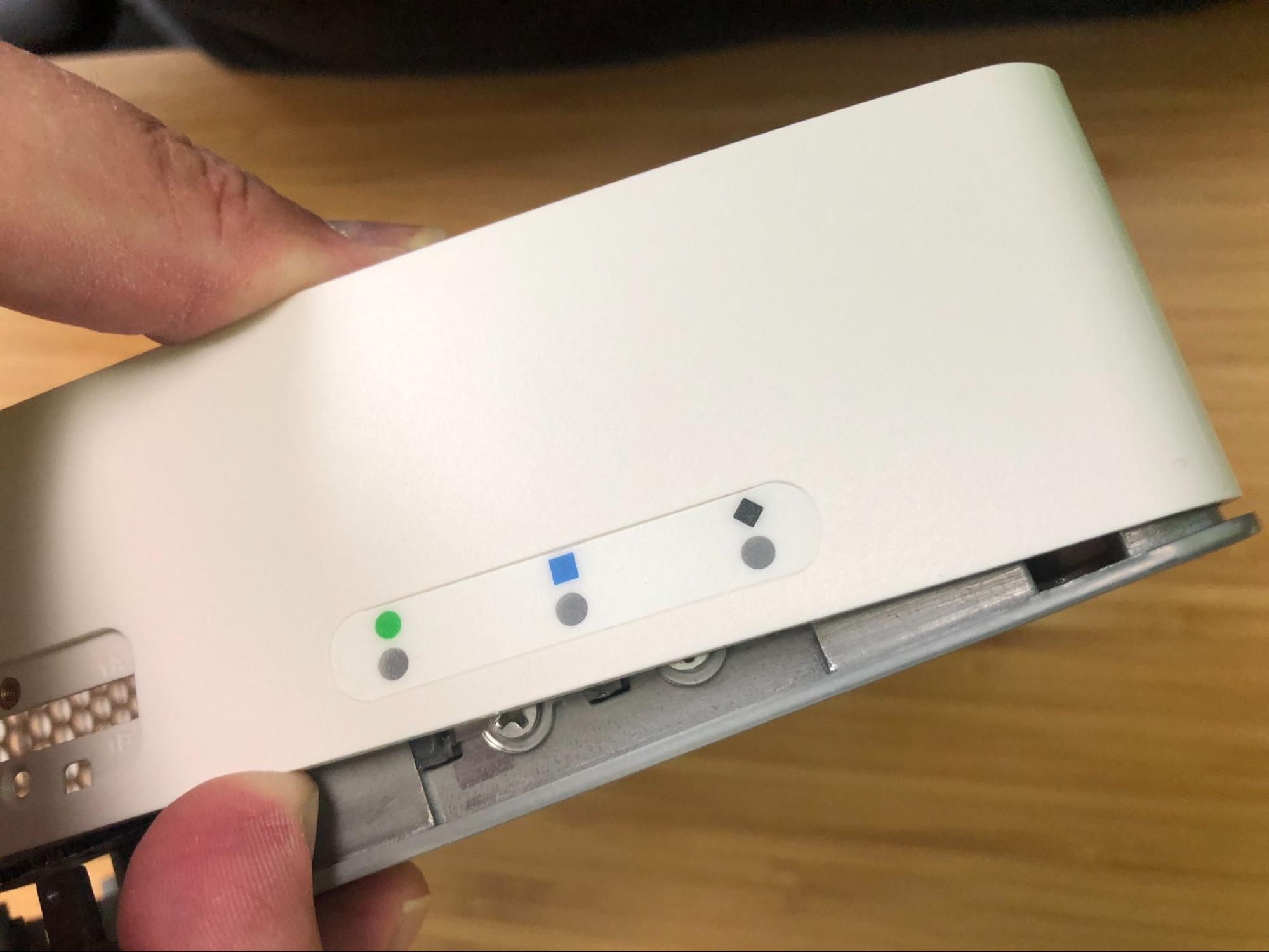
Gently pull the edge of the plastic lid at the front of the device away from the base only far enough for the lid to clear the LED guides and the SIM card slots.
Separating the lid from the LED guides
Continue to work around to the other side of the chassis, pulling and separating.
The lid will fully separate from the chassis.
Set the lid off to the side, keeping it upright to avoid damaging the top surface.
Turn the chassis upright so that the system board is visible.
Set the upright system flat on its base.
Turn the device so the I/O panel (“rear” of the system) is visible.
Install the SSD
Now that the lid is removed, it is time to install the SSD.
Danger
Reminder:
Anti-static protection must be used throughout this procedure.
Any hardware damage incurred during this procedure is not covered by the hardware warranty.
Locate M.2 socket #3 labeled J13. This is the socket in which the M.2 NVMe SSD will be installed.
Note
As mentioned earlier in this document and in Which M.2 card sockets are compatible with an M.2 PCIe NVMe SSD?, the Netgate 4200 is compatible with M.2 B+M-Key or M-Key PCIe NVMe SSDs only in socket #3 labeled J13. This is the rear socket nearest to the I/O panel.
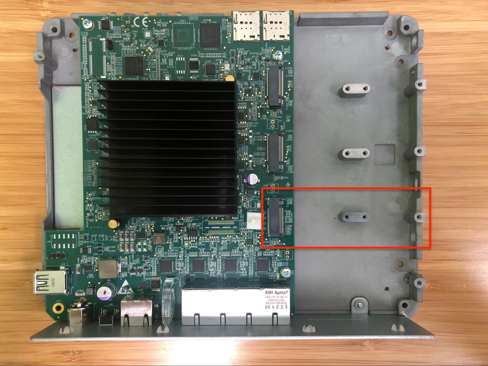
Netgate 4200 top-down internal view with M.2 socket #3 (J13) highlighted
Insert the M.2 card into socket #3 (J13) at an approximate 30° angle
Warning
M.2 cards are keyed. Do not force an M.2 card into a slot with mismatched keying.
Refer to M.2 Edge Connector Keying for a depiction of the different M.2 key types.
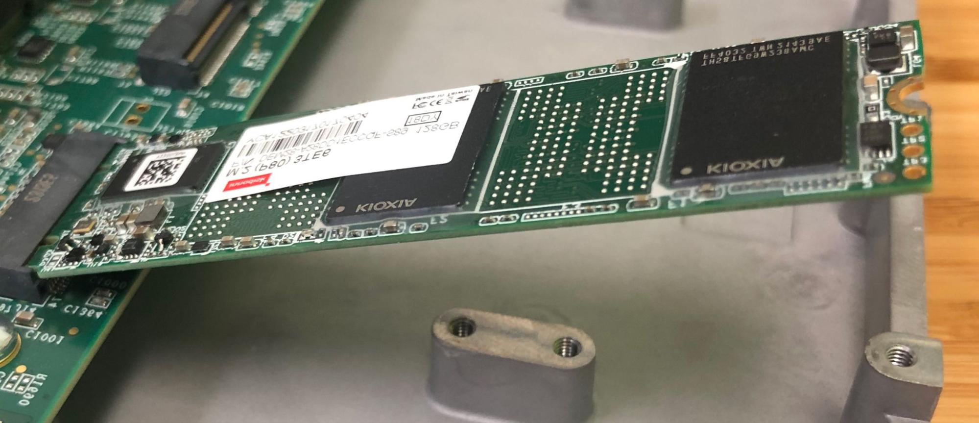
Inserting the SSD into M.2 socket #3 (J13) at an angle
Gently push down the M.2 NVMe card until it reaches the retention screw hole.
Insert the retention screw into the standoff and tighten using the #1 Phillips head screwdriver.
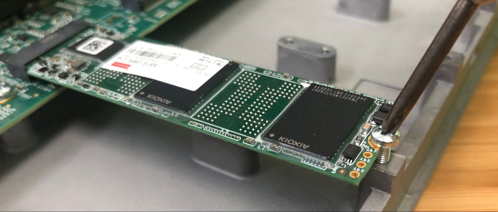
Fastening the M.2 NVMe card retention screw
Replacing and Fastening the Lid
With the M.2 NVMe SSD in place, the next step is to replace the lid and all the fasteners.
Danger
Reminder:
Anti-static protection must be used throughout this procedure.
Any hardware damage incurred during this procedure is not covered by the hardware warranty.
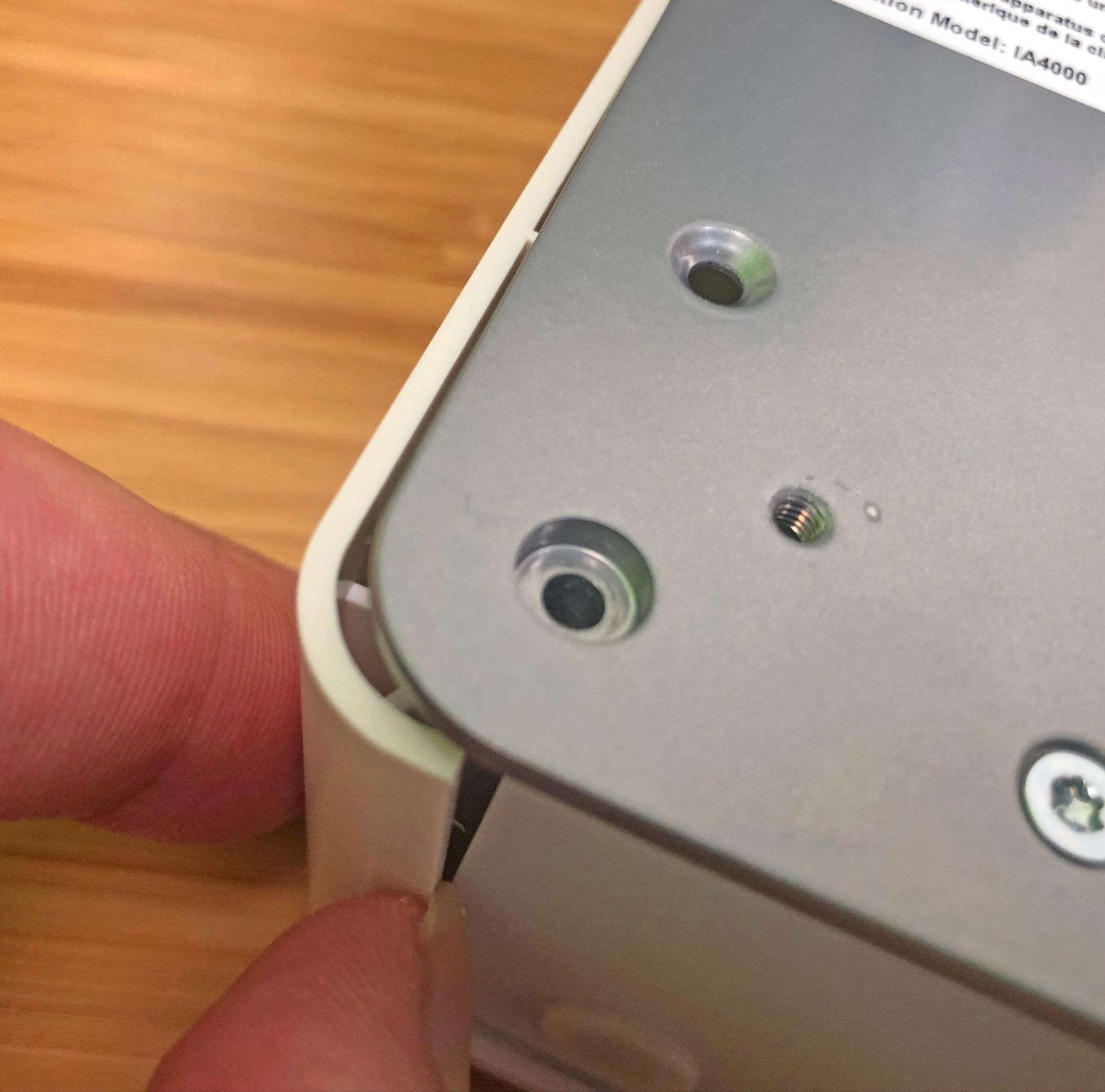
Align the internal groove in the lid with the edges of the I/O panel.
Lower the left edge of the lid onto the chassis.
Aligning the left edge of the lid with the I/O panel
Continue lowering the lid, turning the system until the front (LED and SIM slot side) is visible.
Replacing the front part of the lid
Gently pry the front of the lid away from the chassis just enough to clear the LED light guides and the SIM card slots while simultaneously squeezing the lid down over the light guides and the SIM slots.
The lid should click into place over the light guides.
Replacing the front part of the lid over the LED guides
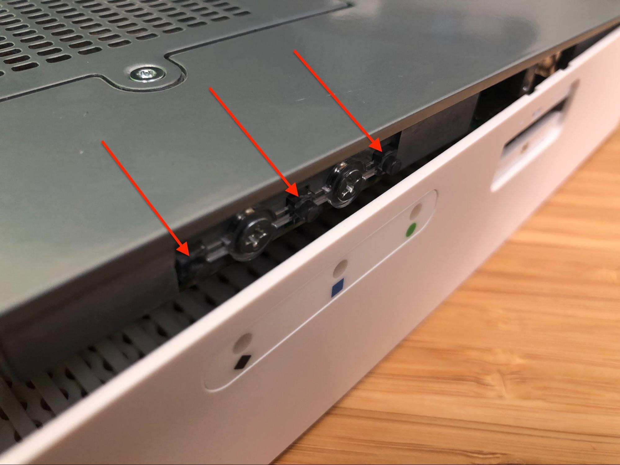
Check the rear corners of the lid to make sure the I/O panel is fully seated in the lid grooves.
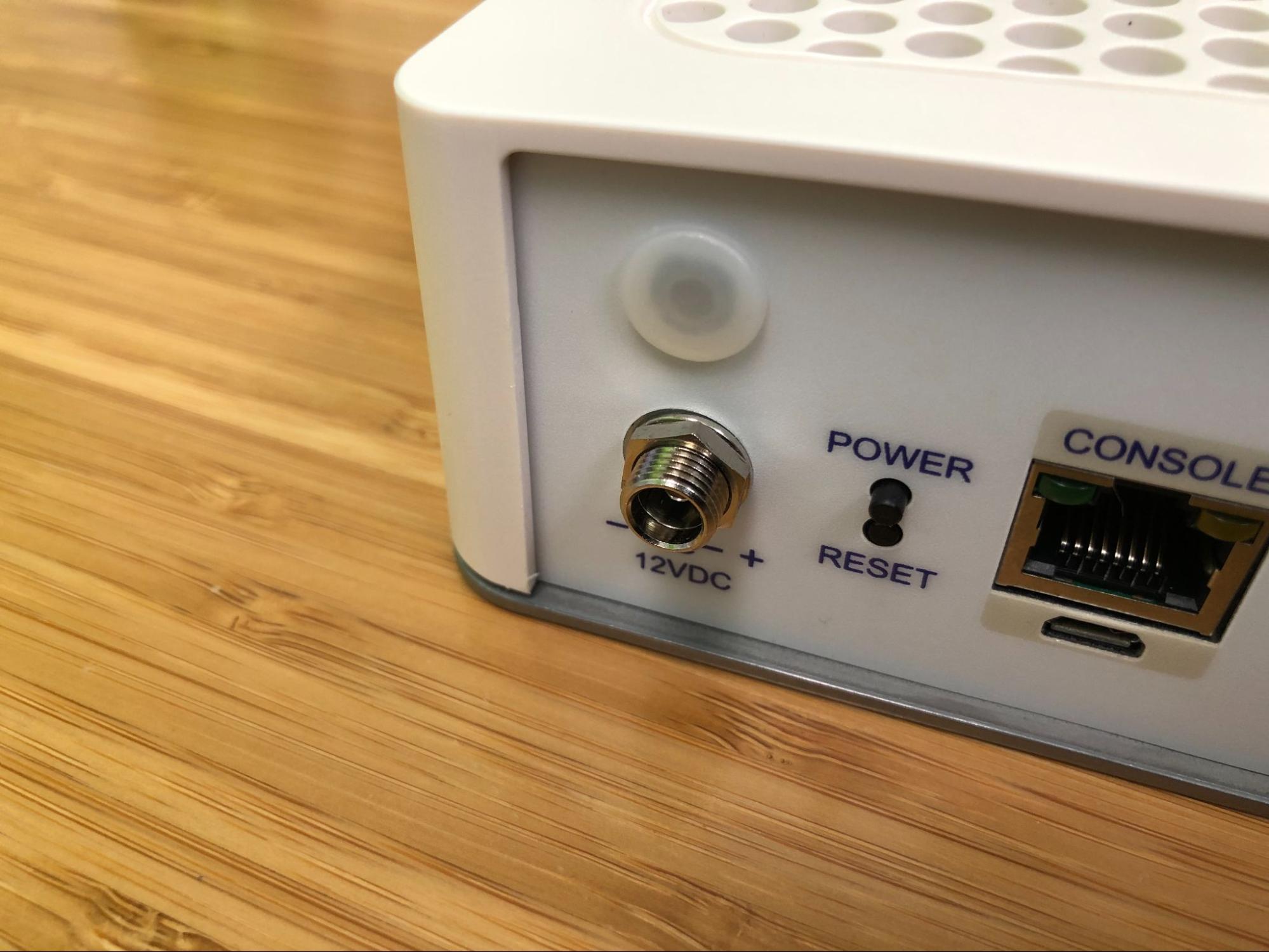
Check the left edge of the I/O Panel
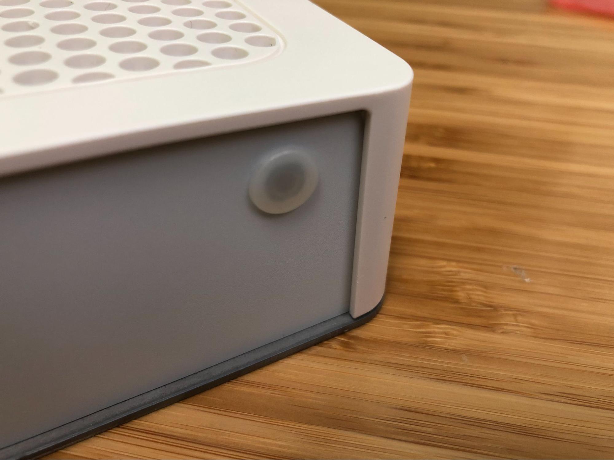
Check the right edge of the I/O Panel
Check the alignment of the plastic lid edges with the metal baseplate, SIM card slots, USB A opening, etc.
Turn the device over carefully and protect the surface to avoid damaging the lid.
Tip
An anti-static mat or similar non-marring work surface is ideal for this role.
Replace the four (4) long T10 Torx plas-tite threaded case screws in the holes (Plas-tite chassis screw locations) using the T10 Torx driver.
Danger
Use caution when replacing the plas-tite threaded case screws. Do not cross thread or over-tighten the screws. Over-tightening the screws can crack and permanently damage the plastic lid.
Plas-tite chassis screw locations
Replace the plastic and rubber feet, fastening them in place with the four (4) T10 Torx machine screws and washers using the T10 Torx driver.
Replace the SIM card slot retention screw using the #1 Phillips screwdriver.
Warning
Use caution when replacing the SIM card slot retention screw. Do not cross thread or over-tighten the screw.
The screw only requires a few gentle turns. Excess force can crack and permanently damage the plastic lid.
Replace the sim card slot cover and retention screw using the #1 Phillips screwdriver.
Warning
Use caution when replacing the SIM card cover retention screw. Do not cross thread or over-tighten the screw.
The screw only requires a few gentle turns. Excess force can crack and permanently damage the slot cover.
Reconnect
The device is now ready to be put back into its former location.
Move the device back to its original location.
Re-mount the Netgate 4200 device if it should be secured in some way (e.g. wall mount)
Plug in all network cables, USB cables and devices, serial console connections, etc.
Insert the USB memstick containing the installation media
Plug in the power cable
Reconnect to the serial console
Reinstall pfSense Plus Software
With the device back together and ready to proceed, the next step is to reinstall pfSense Plus software to the SSD. This procedure is covered in detail in Reinstalling pfSense Plus Software.
Note
If prompted to select a drive during the installation, choose the NVMe drive
which will be nda0. The installer will typically select this drive
automatically, but double check to be certain it is correct.
The eMMC drive (da0 or da1) should remain deselected so it will
not be used by the installer.
If there is no backup to restore, then no further steps are necessary. Login to the firewall and configure it as normal (Initial Configuration).
Restore the Configuration
The final step is to restore the configuration. If a configuration was backed up earlier in this procedure, now is the time to restore it using the GUI or one of the other methods mentioned in the pfSense software documentation section on Backup and Restore.