Configuring the Switch Ports
This optional guide shows the steps required to configure the 4 switched Ethernet ports as discrete ports.
The following attributes are used in this configuration guide but can be changed to suit other requirements:
SG-3100 Ethernet Port: LAN4
IP Address Assignment:
192.168.100.1/24VLAN Tag:
4084(VLAN tags should be4081-4084for LAN Ports 1-4)
Note
When connecting to the GUI, do NOT connect to any port being configured during this procedure or the device will lose connectivity to the GUI.
Open the pfSense® Plus software GUI and log in.
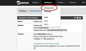
From the menu, navigate to Interfaces > Assignments.
Go to the VLANs tab.
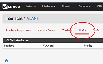
In the lower right-hand corner of the screen, click + Add.
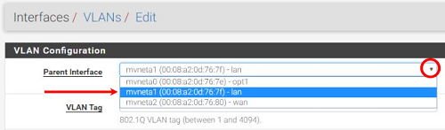
Choose mvneta1 (MAC Address) - lan from the Parent Interface drop-down menu.
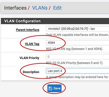
Set the VLAN Tag to 4084. Type LAN port 4 as the Description. Click Save.
Note
This guide uses
4084as an example. The value for the tags must be unique for each VLAN and must be between1and4094. Avoid using values that are already in use. Best practice is not to use1.Go to the Interface Assignments tab.
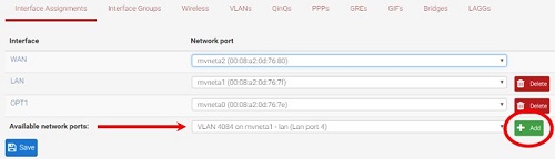
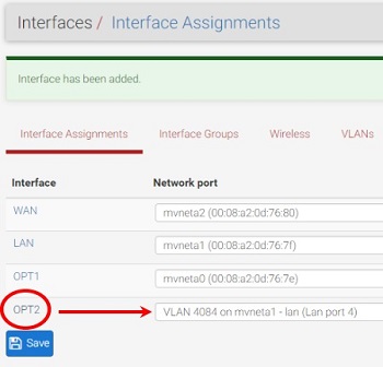
Ensure Available network ports: is correct. It is VLAN 4084 on mvneta1 - lan (LAN port 4) in this example. Click on + Add.
Click on OPT2. This is the Interface that matches the new VLAN being created.
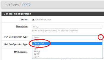
Check the Enable Interface check-box.
Change the IPv4 Configuration Type from None to Static IPv4.
Scroll down and make the IPv4 Address
192.168.100.1/24(in this example).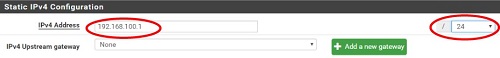
Click Save.
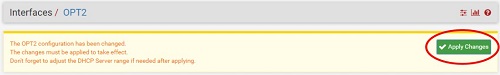
Click Apply Changes.
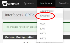
Go to Interfaces > Switches.
Go to the VLANs tab. Click in the Enable 802.1q VLAN mode check-box and click Save.
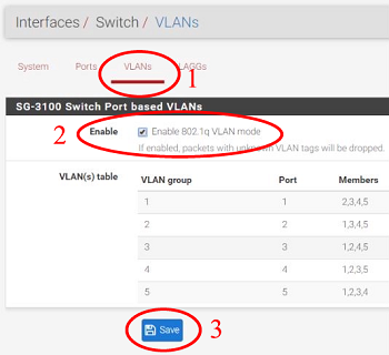
The table will change to reflect the new mode.
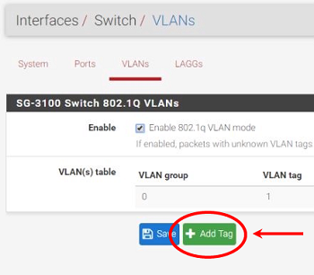
Click + Add Tag.
Type
4084for the VLAN Tag and4for Member(s). This represents LAN4 (port 4) and tagged should be unchecked.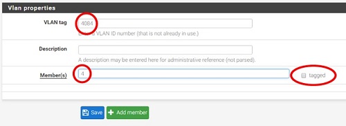
Click + Add Member to add the LAN Uplink, 5. This member should be tagged as shown.
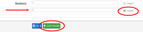
Click Save.
Click on
 beside VLAN group 0.
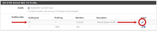
Click Delete beside Member(s) 4. This will remove LAN4 from this VLAN group.
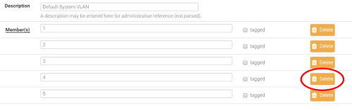
Click Save.
Go to the Ports tab.
Click on Port VID 1 beside LAN4. Backspace through
1and insert4084, the new VLAN ID.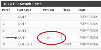
Click Save.
This completes the configuration of a discrete port on the SG-3100.
By default, all traffic is blocked. Create the appropriate firewall rules to allow the traffic. Go to Firewall > Rules and then the OPT2 tab (in this example) to configure the firewall rules.
Enable DHCP if necessary by going to Services > DHCP Server, OPT2 tab (for this example).