Opening and Closing the Netgate 8300 Chassis

Some tasks may require opening up the chassis on the Netgate 8300 to access internal components. This document covers all steps required to open and close the chassis.

Warnings and Precautions

Danger

Anti-static protection must be used throughout this procedure.

Danger

Take all appropriate precautions and exercise care when handling the exposed system board and add-on cards. There are many delicate components which can be damaged during this process. Damage caused via physical contact and electrostatic discharge while performing this installation is not covered by the warranty.

Warning

This device includes an intrusion detection sensor which operates even when the device is without power.

Opening the case on this device triggers an intrusion alarm which is logged by the BMC and is visible in the IPMI sensors. This alarm must be reset manually as described in Re-arm the Chassis Intrusion Switch.

When the intrusion alarm is active the fans run at a fixed speed of around 8500 RPM. Resetting the intrusion sensor alarm returns the fans to their profiled speed.

Required Tools and Hardware

Opening and closing the Netgate 8300 chassis requires the following tools and hardware:

  • Phillips screwdriver

  • Anti-static grounding strap and anti-static mat for handling the 8300 system

Opening the Chassis

Power Off and Disconnect

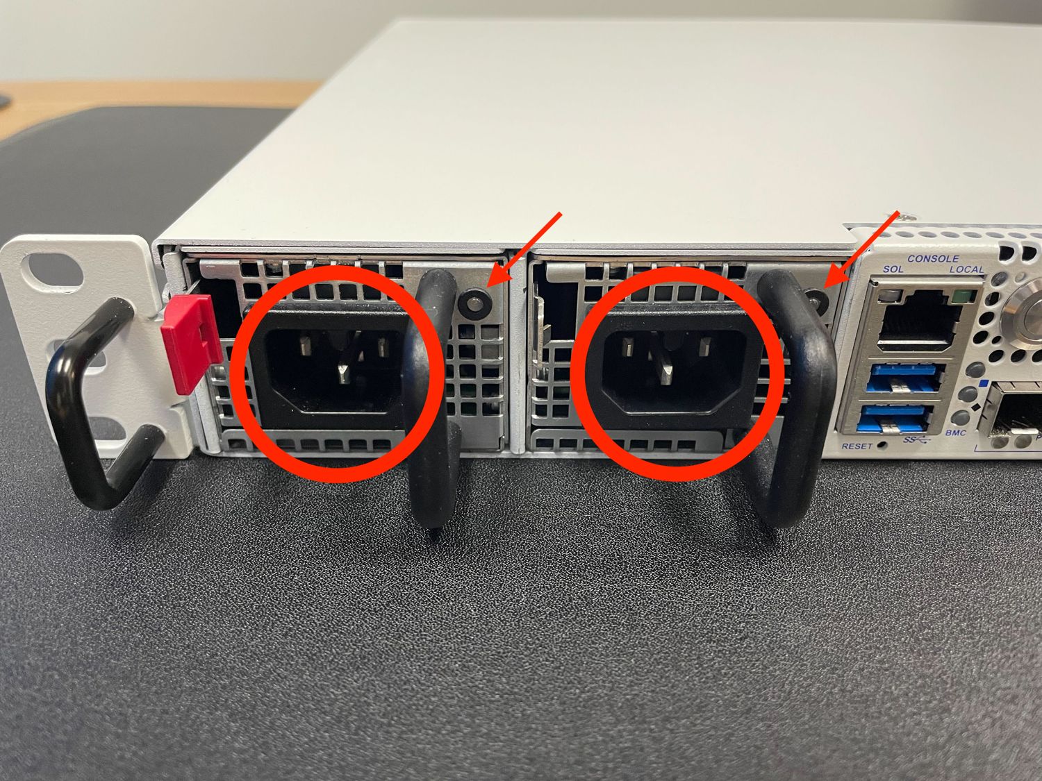
For safety, before opening the case, the Netgate 8300 must be completely disconnected. This includes power, network cables, USB cables, serial console cables, and any other external cables or devices connected to the Netgate 8300.

Danger

Reminder:

  • Anti-static protection must be used throughout this procedure.

  • Any hardware damage incurred during this procedure is not covered by the hardware warranty.

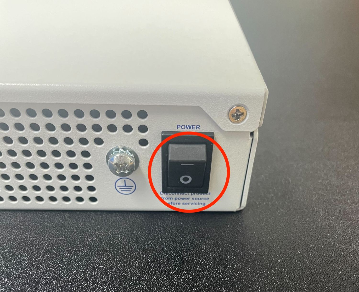
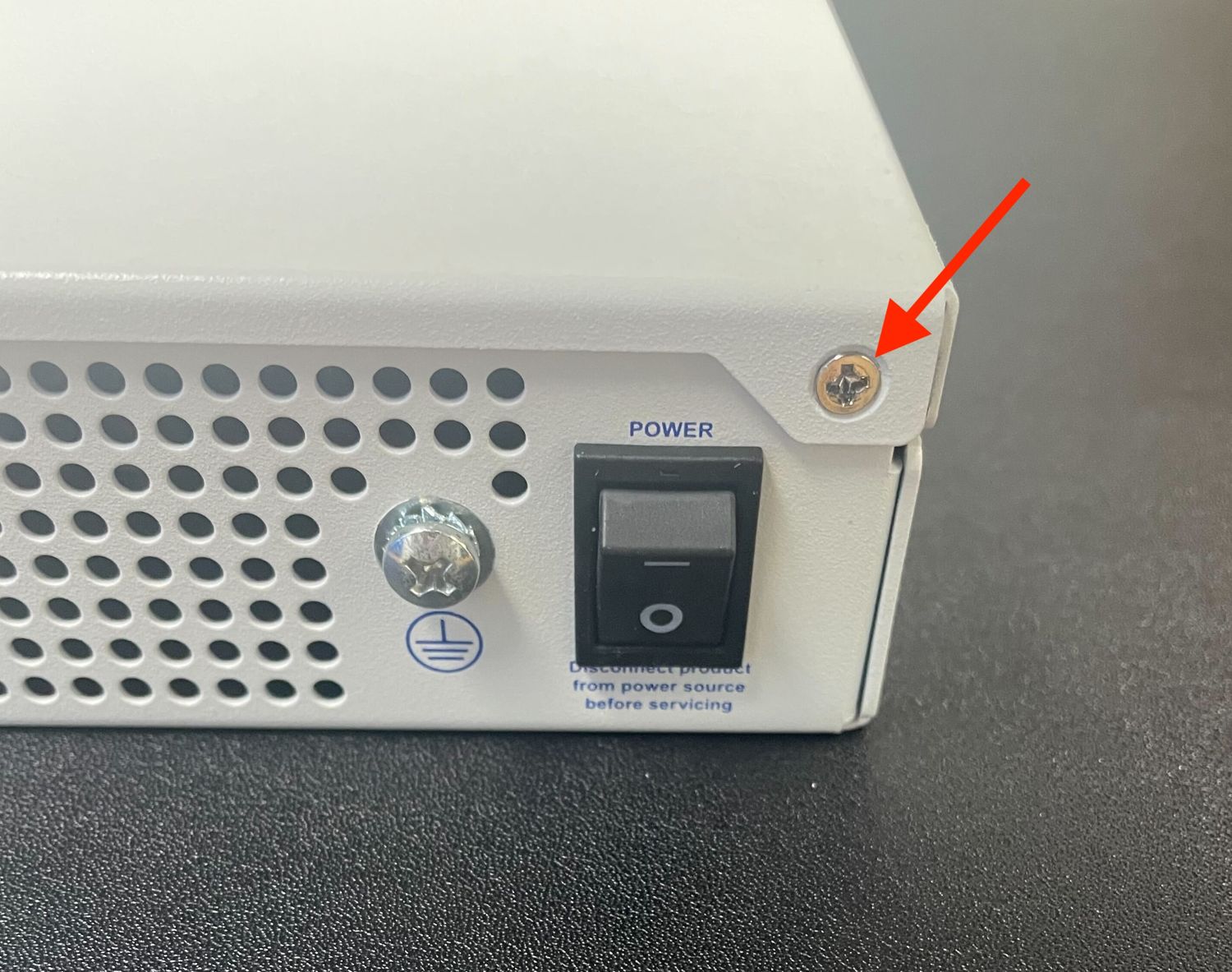
  1. Turn power off to the unit by changing the power switch on the rear of the unit to the off position.

    ../_images/netgate-8300-power-switch.jpg

    Power switch (circled) in the off position

  2. Unplug the power cables from all installed power supply units (PSUs).

    ../_images/netgate-8300-power-cables.jpg

    Power Supply Units with power receptacles circled and status LEDs indicated with arrows

    Danger

    Wait at least 60 seconds after unplugging power to proceed. This ensures that all phantom power has dissipated.

    The LED indicator on all installed PSUs should be off before proceeding.

  3. Unplug all network cables, USB cables and devices, serial console connections, etc.

  4. Dismount the Netgate 8300 from the rack

  5. Move the Netgate 8300 to a safe work location such as an anti-static mat

Removing the Lid

The next portion of the procedure involves opening the device and removing the lid.

Danger

Reminder:

  • Anti-static protection must be used throughout this procedure.

  • Any hardware damage incurred during this procedure is not covered by the hardware warranty.

  1. Remove the screws from the top of the case near the front of the unit using the Phillips head screwdriver.

    ../_images/netgate-8300-top-screws.jpg

    Screws on the top of the cover at the front of the unit, indicated with arrows

  2. Remove the screw from the rear side of the unit at the top left corner using the Phillips head screwdriver.

    ../_images/netgate-8300-rear-left-screw.jpg

    Screw on the rear side of the unit at the left top corner, indicated with an arrow.

  3. Remove the screw from the rear side of the unit at the top right corner using the Phillips head screwdriver.

    ../_images/netgate-8300-rear-right-screw.jpg

    Screw on the rear side of the unit at the right top corner, indicated with an arrow.

  4. Slide the top cover back away from the front panel until it stops.

    ../_images/netgate-8300-cover-slide-notch.jpg

    Sliding back the top cover away from the front panel

  5. Lift off the top cover and set it aside, keeping it upright to avoid damaging the top surface.

    ../_images/netgate-8300-cover-remove.jpg

    Top cover in position to be lifted off

Closing the Chassis

Replacing and Fastening the Lid

With the internal components all in place, the next step is to replace the lid and all its fasteners.

Danger

Reminder:

  • Anti-static protection must be used throughout this procedure.

  • Any hardware damage incurred during this procedure is not covered by the hardware warranty.

  1. Align the top cover with the top of the unit, a short distance behind the front panel.

    ../_images/netgate-8300-cover-remove.jpg

    Top cover in position to be replaced

  2. Slide the top cover toward the front of the unit into its closed position.

    ../_images/netgate-8300-cover-slide-notch.jpg

    Slide the top cover back toward the front panel

# Replace the screws on the rear of the unit (left and right top corners) using

the Phillips head screwdriver.

../_images/netgate-8300-rear-left-screw.jpg

Screw on the rear side of the unit at the left top corner, indicated with an arrow.

../_images/netgate-8300-rear-right-screw.jpg

Screw on the rear side of the unit at the right top corner, indicated with an arrow.

# Replace the screws on the top of the unit using the Phillips head screwdriver.

../_images/netgate-8300-top-screws.jpg

Screws on the top of the cover at the front of the unit, indicated with arrows

Reconnect

The device is now ready to be put back into its former location.

  1. Mount the Netgate 8300 in the rack

  2. Plug in all network cables, USB cables and devices, serial console connections, etc.

  3. Insert the USB memstick containing the installation media

  4. Plug the power cables into all installed power supply units.

    ../_images/netgate-8300-power-cables.jpg

    Power Supply Units with power receptacles circled and status LEDs indicated with arrows

  5. Turn power on to the unit by changing the power switch on the rear of the unit to the on position.

  6. Reconnect to the serial console

Re-arm the Intrusion Sensor

Opening the case triggers the intrusion alarm sensor, even when the device is removed from power. The intrusion alarm causes the fans to run at a higher fixed speed until the sensor is re-armed.

Follow the procedure in Re-arm the Chassis Intrusion Switch to reset the sensor once the operating system is running.