Configuring an OPT interface as an additional LAN
Note
The default configuration has all ports assigned as WANs and LANs to match the labels on the back of the device. These are only pre-defined labels; any port can be renamed and configured for any purpose.
This guide configures an OPT port as an additional LAN type interface. These local interfaces can perform a variety of tasks, such as being a guest network, DMZ, IOT isolation, wireless segment, lab network, and more.
Requirements
This guide assumes the underlying interface is already present (e.g. physical port, VLAN, etc.).
Choose a new local subnet to use for the additional LAN type interface. This example uses
192.168.2.0/24.
Assign the Interface
The first step is to assign an OPT interface.
Navigate to Interfaces > Assignments
Look at list of current assignments. If the interface in question is already assigned, there is nothing to do. Skip ahead to the interface configuration.
Pick an available interface in Available network ports
If there are no available interfaces, then one may need to be created first (e.g. VLANs).
Click
 Add
Add
The firewall will assign the next available OPT interface number corresponding to the internal interface designation. For example, if there are no current OPT interfaces, the new interface will be OPT1. The next will be OPT2, and so on.
Note
As this guide does not know what that number will be on a given configuration, it will refer to the interface generically as OPTx.
The newly assigned interface will have its own entry under the Interfaces menu and elsewhere in the GUI.
Interface Configuration
The new interface must be enabled and configured.
Navigate to Interfaces > OPTx
Check Enable interface
Set custom name in the Description, e.g.
GUESTS,DMZ, etc.Set the IPv4 Address and CIDR mask for the new LAN
For this example,
192.168.2.1/24.Do not add or choose an IPv4 Upstream gateway
Uncheck Block private networks
This interface is a private network, this option would prevent it from functioning.
Uncheck Block bogon networks
The rules on this interface should only allow traffic from the subnet on the interface, making this option unnecessary.
Click Save
Click Apply Changes
The lack of a selected gateway in the interface configuration causes the firewall to treat the interface as a LAN type interface.
The firewall uses LAN type interfaces as sources of outbound NAT traffic but does not apply outbound NAT on traffic exiting a LAN. The firewall does not add any extra properties on firewall rules to influence traffic behavior. The DNS Resolver will accept queries from clients on LAN type interfaces.
See also
DHCP Server
Next, configure DHCP service for this local interface. This is a convenient and easy way assign addresses for clients on the interface, but is optional if clients will be statically addressed instead.
This configuration varies slightly depending on the DHCP server and version.
See also
Navigate to Services > DHCP Server, OPTx tab (or the custom name)
Check Enable
Configure the Address Pool Range, e.g. from
192.168.2.100to192.168.2.199This sets the lower (From) and upper (To) bound of automatic addresses assigned to clients.
The rest of the settings can be left at defaults
Click Save
Outbound NAT
For clients on this interface to reach the Internet from private addresses, the firewall must apply Outbound NAT for the new subnet.
Navigate to Firewall > NAT, Outbound tab
Check the current outbound NAT mode and follow the section below which matches the mode.
Automatic or Hybrid Outbound NAT
If the mode is set to Automatic or Hybrid, then this likely does not need further configuration.
Ensure the new LAN subnet is listed as a Source in the Automatic Rules at the bottom of the page. If so, skip ahead to the next section to configure Firewall Rules.
Manual Outbound NAT
If the mode is set to Manual, create a new rule or set of rules to cover the new subnet.
Click
 to add a new rule at the top of the list
Configure the rule as follows:
- Interface:
Choose the WAN interface. If there is more than one WAN interface, add separate rules for each WAN interface.
- Address Family:
IPv4
- Protocol:
Any
- Source:
Either choose OPTx Subnets, which will automatically reference the new interface, or choose Network or Alias and manually fill in the new subnet, e.g.
192.168.2.0/24.- Destination:
Any
- Translation Address:
WAN Address (or the customized name matching the WAN/egress interface)
- Description:
Text describing the rule, e.g.
Guest LAN outbound on WAN
Click Save
Click Apply Changes
Alternately, clone existing NAT rules and adjust as needed to match the new LAN.
Firewall Rules
By default, there are no firewall rules on the new interface, so the firewall will block all traffic. This is not ideal for a LAN as generally speaking, the clients on this LAN will need to contact hosts through the firewall.
Rules for this interface can be found under Firewall > Rules, on the OPTx tab (or the custom name, e.g. GUESTS).
There are two common scenarios administrators typically choose for local interfaces: Open and Isolated
Open
On an open LAN, hosts in that LAN are free to contact any other host through the firewall. This might be a host on the Internet, across a VPN, or on another local LAN.
In this case a simple “allow all” style rule for the interface will suffice.
Navigate to Firewall > Rules, on the OPTx tab (or the custom name)
Click
to add a new rule at the top of the listConfigure the rule as follows:
- Action:
Pass
- Interface:
OPTx (or the custom name) should already be set by default
- Protocol:
Any
- Source:
OPTx subnets (or the custom name)
- Destination:
Any
- Description:
Text describing the rule, e.g.
Default allow all from OPTx
Click Save
Click Apply Changes
Isolated
In an isolated local network, hosts on the network cannot contact hosts on other networks unless explicitly allowed in the rules. Hosts can still contact the Internet as needed in this example, but that can also be restricted with additional rules.
This scenario is common for locked down networks such as for IOT devices, a DMZ with public services, untrusted Guest/BYOD networks, and other similar scenarios.
Warning
A full set of reject rules as described in this example is the best practice. Do not rely on shortcuts such as using policy routing to isolate clients.
Create a Private Networks Alias
Create an alias using all RFC 1918 networks (listed in the example below) or at least an alias containing the local/private networks on this firewall, such as VPNs. Using all RFC 1918 networks is a safer practice.
Navigate to Firewall > Aliases
Click
AddConfigure the alias as follows:
- Name:
PrivateNets- Description:
Private Networks- Type:
Network(s)
Add entries for:
192.168.0.0/16172.16.0.0/1210.0.0.0/8
Click Save
Add Firewall Rules
With the alias in place, the next task is to create firewall rules for the interface.
Navigate to Firewall > Rules, on the OPTx tab (or the custom name)
Allow DNS
Add rule to allow DNS requests from local clients to the firewall itself or other DNS servers.
Click
 to add a new rule at the bottom of the list.
Configure the rule as follows:
- Action:
Pass
- Interface:
OPTx (or the custom name)
- Protocol:
TCP/UDP
- Source:
OPTx subnets (or the custom name)
- Destination:
This Firewall (self)
If clients are configured to query DNS servers other than this firewall, create rules using those as the destination instead.
- Destination Port Range:
Select the DNS (53) entry or choose Other and manually enter
53To allow DNS over TLS, create a separate rule using the DNS over TLS entry or manually enter port
853.- Description:
Text describing the rule, e.g.
Allow clients to resolve DNS through the
firewall
Click Save
Allow ICMP to the Firewall
Add a rule to allow ICMP traffic from local devices to the firewall.
Click
to add a new rule at the bottom of the list.Configure the rule as follows:
- Action:
Pass
- Interface:
OPTx (or the custom name)
- Protocol:
ICMP
- ICMP Subtype:
Any
Tip
While ICMP is useful, some network administrators prefer to limit the allowed ICMP types to Echo Request only. This allows devices to use ICMP ping for diagnostic purposes, but no other types of ICMP traffic.
- Source:
OPTx subnets (or the custom name)
- Destination:
This Firewall (self)
- Description:
Allow client ICMP to the firewall
Click Save
Reject Other Firewall-bound Traffic
Add rule to reject any other traffic to the firewall to ensure users on this interface cannot connect to management services such as the GUI, SSH, and so on.
Click
to add a new rule at the bottom of the list.Configure the rule as follows:
- Action:
Reject
- Interface:
OPTx (or the custom name)
- Protocol:
Any
- Source:
Any
- Destination:
This Firewall (self)
- Description:
Reject all other traffic to the firewall
Click Save
Reject Private Traffic
Add rule to reject traffic from this network to all other private networks.
Click
to add a new rule at the bottom of the list.Configure the rule as follows:
- Action:
Reject
- Interface:
OPTx (or the custom name)
- Protocol:
Any
- Source:
Any
- Destination:
Address or Alias,
PrivateNets(the alias created earlier)- Description:
Reject all other traffic to private networks
Click Save
Allow Other Traffic
Add rule to allow traffic from this interface network to any other destination, which enables clients on this interface to reach the Internet and/or other remote public networks.
Click
to add a new rule at the bottom of the list.Configure the rule as follows:
- Action:
Pass
- Interface:
OPTx (or the custom name)
- Protocol:
Any
- Source:
OPTx subnets (or the custom name)
- Destination:
Any
- Description:
Default allow all from OPTx
Click Save
Apply Changes
With the rules all in place, click Apply Changes to finish and activate the new rules.
The rules should look similar to the following figure:
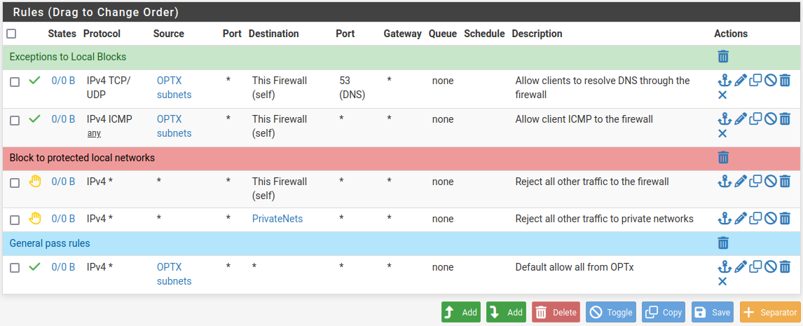
Example firewall rules for isolated LAN type segment
Tip
Rule separators are useful for documenting a ruleset in place.
Similar to the isolated network scenario, it is also possible to be much more strict with rules to only allow specific outbound ports. When creating this type of configuration,
Other Services
In most cases the above configuration is sufficient and clients on the new LAN can now obtain an address and reach the Internet. However, there may be other custom settings which need accounted for when adding a new local interface:
If the DNS resolver has specific interface bindings, add the new interface to the list.
If using ALTQ traffic shaping, re-run the shaper wizard to include this new LAN type interface.
Consider using captive portal to control access the interface