Netgate 4100 Rack Mount
The Netgate 4100 has an optional Rack Mount Kit available. This page provides an overview for attaching the system to the rack mount.
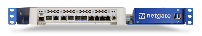
The Netgate 4100 Rack Mounted
Note
The Rack Mount Kit is identical for the Netgate 4100, the Netgate 6100, and the Netgate 8200.
The Netgate 4100 Rack Mount Kit contains all the components necessary to mount the Netgate 4100.
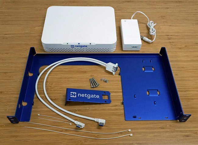
The Netgate 4100 Rack Mount Kit
The kit contains:
1 Anodized Rack Chassis
1 Rack Faceplate
1 USB 3.0 panel mount cable (pre-attached to the faceplate)
1 M3 Phillips flat head thread rolling screw
4 M4 x 40mm Socket Head Cap Screws (Hex / Allen drive)
2 Long Cable Ties (11.5”)
2 Short Cable Ties (3”)
Note
The Kit does not include the Netgate 4100, nor does it include the AC/DC Power Supply Brick.
Tools required:
#1 Philips Screwdriver
3mm Hex Key (Allen) Wrench
Rack Mount Assembly Instructions
Insert the tabs on the right edge of the faceplate with the two slots in the right front corner of the rack mount chassis.
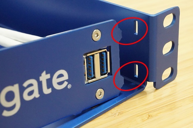
Line up and Insert the Tabs to the Slots on the Right
Align the tabs on the bottom edge of the faceplate and insert into the two slots in the bottom of the chassis.
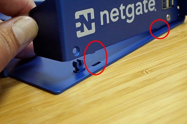
Line up and Insert the Tabs to the Slots on the bottom
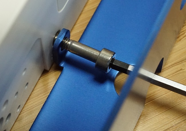
Using a Philips screwdriver, gently thread the screw until the screw is fully inserted, and the head stops flush with the faceplate.
Warning
Do not overtighten.
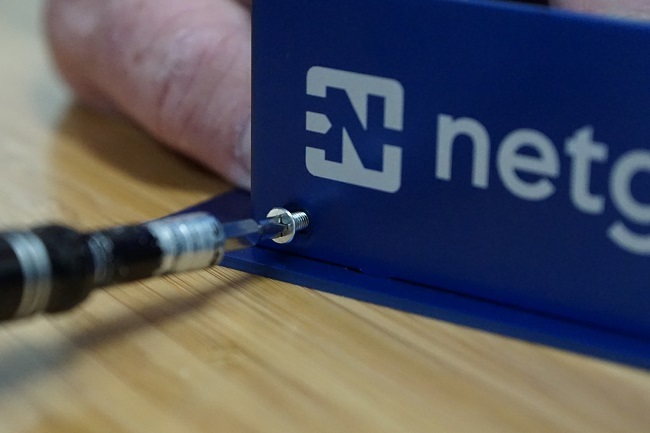
Insert the Screw
If converting a desktop appliance to a rack mount system, remove the rubber feet from the bottom of the desktop unit.
Note
It is important to remove the feet, especially for racking something in the slot directly below the Netgate appliance.
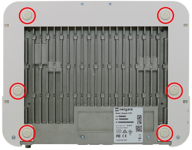
Remove the Rubber Feet
With the rubber feet removed, line up the mounting holes in the system housing with the mounting tabs on the rack mount.
Note
The LEDs face the rear, the ports face the front, as shown. The system cannot be reversed without potential damage to the appliance.
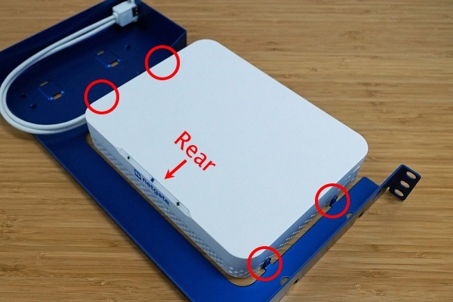
Appliance Lined up with the Rack Mount
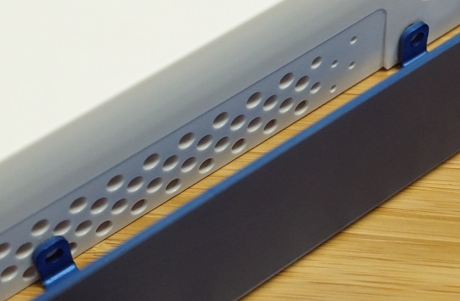
Close-up of Alignment
Insert the M4 x 40mm socket head cap screws into the tabs and mounting holes. Using a 3mm hex key, gently tighten the M4 socket head screws.
Warning
Do not overtighten.
Repeat for all Four Mounting Holes
Place 1 large cable tie through each of the large holes in the chassis.
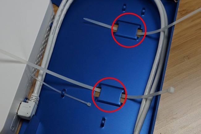
Insert 11.5” Cable Ties
Place the power supply as shown and tighten the cable ties. Also add the small 3” cable tie as shown in the picture.
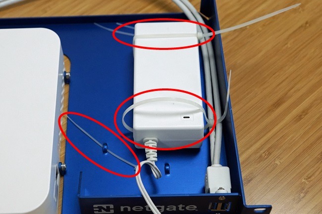
Tighten the Cable Ties. Add the Small Cable Tie as Shown.
Using a small cable tie, loosely fasten the bundle of Power Supply output wires to the chassis as shown below.
Do not Cinch Down the Cable Tie Yet
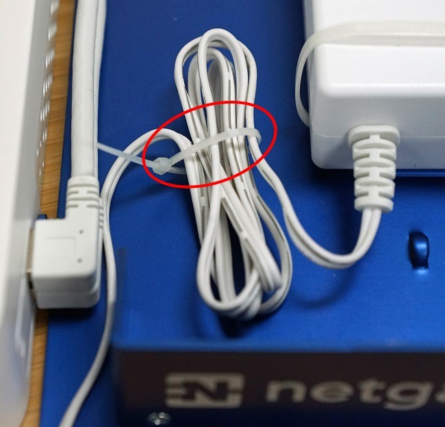
Connect the power input jack on the front of the system and adjust the length of the power wire to remove any tension.
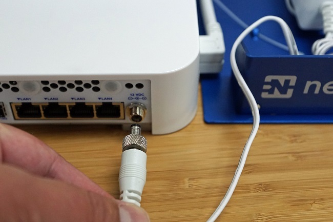
Do Not Put Tension On The Cable. The Cable Should Have Enough Length to be Removed Without Excessive Tension.
Pull the cable ties tightly around the power supply and the wire bundle. Cut the cable ties.
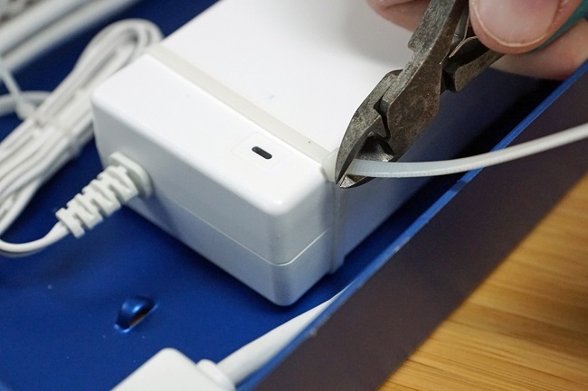
Cut the Excess Cable Ties
Plug in the USB cable extenders.
Note
Angling the USB connectors slightly can avoid the need to remove the front faceplate when inserting USB cables.
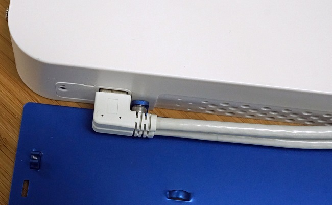
Plug in the USB Cable Extenders
The Netgate 4100 Rack Mount is ready to install into the rack.