Layer 2 Redundancy
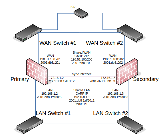
The diagrams earlier in this chapter did not describe layer 2 (switch) redundancy, to avoid throwing too many concepts at readers simultaneously. This section covers the layer 2 design elements to be considered when planning a redundant network. This document assumes a two node deployment.
If both redundant nodes running pfSense® software are plugged into the same switch on any interface, that switch becomes a single point of failure. To avoid this single point of failure, the best choice is to deploy two switches for each interface (other than the dedicated Sync interface).
Example High Availability Cluster Network Diagram is network-centric, not showing the switch infrastructure. The Figure Diagram of HA with Redundant Switches illustrates how that environment looks with a redundant switch infrastructure.

Diagram of HA with Redundant Switches
Switch Configuration
When using multiple switches, the switches should be interconnected. As long as there is a single connection between the two switches, and no bridge on either of the firewalls, this is safe with any type of switch. Where using bridging, or where multiple interconnections exist between the switches, care must be taken to avoid layer 2 loops. A managed switch would be required which is capable of using Spanning Tree Protocol (STP) to detect and block ports that would otherwise create switch loops. When using STP, if an active link dies, e.g. switch failure, then a backup link can automatically be brought up in its place.
pfSense software can utilize lagg(4) link aggregation and link failover interfaces. This feature allows multiple network interfaces to be plugged into one or more switches for increased fault tolerance.
See also
See LAGG (Link Aggregation) for more information on configuring link aggregation.
Host Redundancy
It is more difficult to obtain host redundancy for critical systems inside the firewall. Each host could have two network cards and a connection to each group of switches using Link Aggregation Control Protocol (LACP) or similar vendor-specific functionality. Servers could also have multiple network connections, and depending on the OS it may be possible to run CARP or a similar protocol on a set of servers so that they would be redundant as well.
Providing host redundancy is more specific to the capabilities of the switches and server operating systems, which is outside the scope of this documentation.
Other Single Points of Failure
When trying to design a fully redundant network, there are many single points of failure that sometimes get missed. Depending on the level of uptime to achieve, there are multiple items to consider beyond a switch failure. Here are a few more examples for redundancy on a wider scale:
Supply isolated power for each redundant segment
Use separate breakers for redundant systems
Use multiple UPS banks/generators
Use multiple power providers, entering opposite sides of the building where possible
Even a Multi-WAN configuration is no guarantee of Internet uptime
Use multiple Internet connection technologies (Fiber, Cable, DSL, Wireless)
If any two carriers use the same pole/tunnel/path, they could both be knocked out at the same time
Have backup cooling, redundant chillers or a portable/emergency air conditioner
Consider placing the second set of redundant equipment in another room, another floor, or another building
Have a duplicate setup in another part of town or another city
I hear hosting is cheap on Mars, but the latency is killer