Switch Ports Overview
This document is an overview of how the switch operates and its capabilities.
For instructions on how to configure the switch in a variety of ways, including configuring the switch ports as isolated independent interfaces, see Configuring the Switch Ports.
Warning
The switch is limited to a total maximum of 128 separate VLANs.
Warning
The switch ports do not implement the Spanning Tree Protocol (STP). Two or more ports connected to another Layer 2 switch, or connected to 2 or more different interconnected switches, could create a flooding loop between the switches. This can cause the router to stop functioning until the loop is resolved.
Interface Links
In addition to two SFP+ interfaces, there is also an Ethernet switch on the
XG-7100. There are eight Ethernet ports on this switch that are physically
accessible – these interfaces are referred to as ETH1-ETH8. In addition to
those 8 ports, there are also three additional ports that operate behind the
scenes - PORT 0, PORT 9 (ix2), and PORT 10 (ix3).
ETH1-ETH8 are gigabit switch ports.
PORT 9-10 are 2.5 Gbps uplink switch ports. These two ports connect the Ethernet
switch to a Denverton SoC. The SFP+ interfaces (ix0 and ix1) also
connect to this SoC.
The diagram below demonstrates how these interfaces are connected:
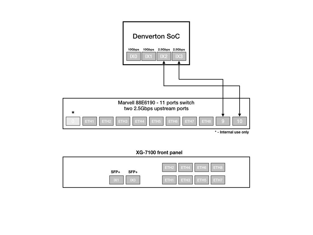
From the perspective of the operating system, there are four physical interfaces present:
ix0 - 10 Gbps SFP+
ix1 - 10 Gbps SFP+
ix2 - 2.5 Gbps (2500-Base-KX, switch link to SoC/CPU)
ix3 - 2.5 Gbps (2500-Base-KX, switch link to SoC/CPU)
Switch LAGG
ix2 and ix3 (switch uplink ports 9 and 10), are configured as a
load-balanced LAGG. This provides an aggregate uplink capable of 5 Gbps for
Ethernet switch ports ETH1-8. This is further demonstrated in the diagram below:
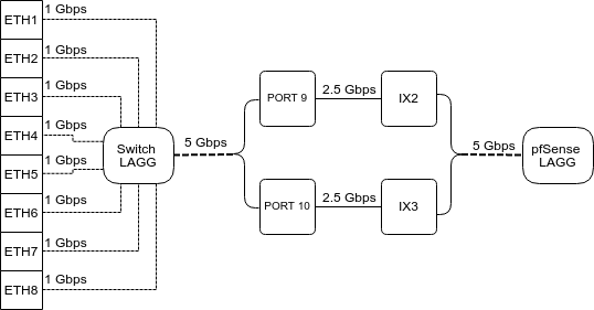
When data is received on ETH1-8, the switch is capable of utilizing LAGG to
determine whether that data should be sent out of PORT 9 or PORT 10. That data
then passes over one of two 2.5 Gbps switch links (PORT 9/10) to the SoC. Data
coming from PORT 9 has a direct line to ix2 and data from PORT 10 has a
direct line to ix3.
pfSense® Plus LAGG will then take in traffic from both ix2 and ix3 as
though it came in on a single interface, lagg0. The same concept applies to
traffic sourcing from the pfSense® Plus LAGG to the switch LAGG.
802.1q VLAN Mode
By default, ETH1 on the switch is configured as a WAN interface and ETH2-8 are configured as the LAN interface. These eight switch ports are customizable and each can be configured to act as an independent interface. For example, all of these configurations are possible:
ETH1-8 dedicated as a LAN switch
ETH1-4 configured as a switch for LAN network A and ETH5-8 configured as a switch for LAN network B
ETH1-8 configured as individual network interfaces
ETH1 configured for WAN A, ETH2 configured for WAN B, ETH3 configured for LAN network A, ETH4-6 configured as a switch for LAN network B, and ETH8 configured as a H/A sync port.
These scenarios are possible by utilizing VLANs. Each of the switch ports (ETH1-8 and PORT9-10) are VLAN aware interfaces. They are capable of functioning like a standard access or trunk port:
- Access Port:
Adds a VLAN tag to inbound untagged traffic
- Trunk Port:
Allows tagged traffic containing specified VLAN IDs
In the default configuration, two VLANs are used to create the ETH1 WAN interface and ETH2-8 LAN interface:
WAN |
VLAN 4090 |
LAN |
VLAN 4091 |
ETH1-8 are configured to act as Access ports.
When data comes into the ETH1 interface, a VLAN tag of 4090 is added to the Ethernet frame.
When data comes into interfaces ETH2-8, a VLAN tag of 4091 is added to the Ethernet frame.
PORT9-10 are configured to act as Trunk ports.
By default, only Ethernet frames containing a VLAN tag of 4090 or 4091 are allowed over the trunk.
Each VLAN configured on the switch uses the LAGG interface as its parent interface. For example, the default interface assignment for WAN and LAN:
WAN |
lagg0.4090 |
LAN |
lagg0.4091 |
This means lagg0.4090 and lagg0.4091, as well as any other VLANs created
for the switch, all share the same 5 Gbps LAGG uplink across two 2.5 Gbps links.
The visual below demonstrates how the VLAN tagging works along with the traffic
flow:
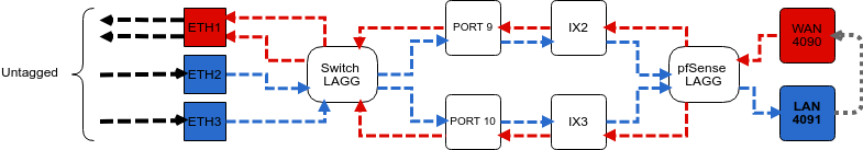
Note
Traffic leaving and entering the ETH1-3 interfaces in the visual above are untagged. Devices sending/receiving traffic over these ports do not need to be VLAN aware. The VLAN tagging that occurs within the switch is completely transparent to clients. It’s used solely for segmenting switch traffic internally.
Port Mode
Aside from being able to specify whether a switch port should act as an access or trunk port, it’s also possible to disable 802.1q VLAN mode. When this is done, a third mode called Port VLAN Mode is enabled. In this mode, any and all VLAN tags are allowed on all ports. No VLAN tags are added or removed. Think of it as a dummy switch that retains VLAN tags on frames, if present. This mode is useful when there are numerous VLANs on a network and the goal is to physically segment the switch, while allowing the same VLANs on all segments of the switch.
In Port VLAN Mode, rather than specifying which interfaces are associated to a VLAN, the configuration can specify which physical ports form a switch. For example, to create two physical switches that act as individual dummy switches - - allowing tagged or untagged traffic, configure Port VLAN Mode like so:
// UPLINKS
VLAN group 9, Port 9, Members 1,2,3,4,10
VLAN group 10, Port 10, Members 1,2,3,4,9

// SWITCH-A
VLAN group 1, Port 1, Members 2,3,4,9,10
VLAN group 2, Port 2, Members 1,3,4,9,10
VLAN group 3, Port 3, Members 1,2,4,9,10
VLAN group 4, Port 4, Members 1,2,3,9,10

// SWITCH-B
VLAN group 5, Port 5, Members 6,7,8
VLAN group 6, Port 6, Members 5,7,8
VLAN group 7, Port 7, Members 5,6,8
VLAN group 8, Port 8, Members 5,6,7
With this configuration in place, ETH1-8 now function like so:
// SWITCH-A
PORT 1 = ETH1
PORT 2 = ETH2
PORT 3 = ETH3
PORT 4 = ETH4
PORT 9 = UPLINK 1
PORT 10 = UPLINK 2

// SWITCH-B
PORT 5 = ETH5
PORT 6 = ETH6
PORT 7 = ETH7
PORT 8 = ETH8
SWITCH-A
ETH1-4 can talk to each other and to the LAGG uplink. PORT9-10 are members of this switch…this is required for this switch to have uplink to pfSense® Plus.
SWITCH-B
ETH5-8 can talk to each other but because PORT9-10 are not included as members,
clients connecting to ETH5-8 can only talk to other clients on ETH5-8. They will
not be able to reach the SoC where ix2 and ix3 are defined, so they
never reach the pfSense® Plus software. This can be useful to allow a device
other than pfSense® Plus to act as the primary uplink for those connected
clients.
Since WAN and LAN are assigned to lagg0.4090 and lagg0.4091, if Port
VLAN Mode is enabled, be sure to update the LAN and WAN interface assignment
to reference the appropriate VLAN. Also remember to create the new VLANs with
lagg0 as the parent interface.
If Port VLAN Mode is being used to handle untagged traffic, the lagg0
interface should be added, enabled, and configured under Interface Assignments.
See also
For more information on how to configure the switch ports, see Configuring the Switch Ports.