Input and Output Ports
Front Side
The front side of the Netgate 5200 contains most items of interest for connecting to and managing the device.
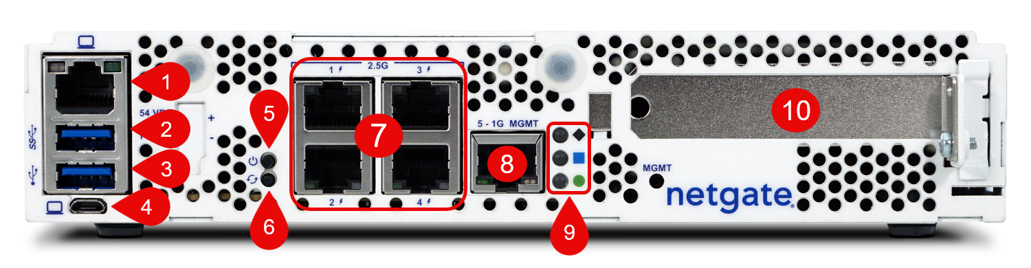
Rear side view of the Netgate 5200 Firewall Appliance
The items below are marked with circled numbers on figure Rear side view of the Netgate 5200 Firewall Appliance:
# |
Description |
Purpose |
|---|---|---|
1 |
RJ45 Serial Port |
|
2 |
USB 3.2 Type-A Port |
Connect USB devices (up to 5Gbps) |
3 |
USB 2.0 Type-A Port |
Connect USB devices (up to 480Mbps) |
4 |
USB Micro-B (5-pin) Serial |
|
5 |
Power Button (Protruding) |
Graceful shutdown, hard power off (Hold 10s), power on |
6 |
Reset Button (Recessed) |
Perform Factory Reset Procedure |
7 |
4x 2.5 Gbps Network Ports |
|
8 |
1x 1 Gbps Network Port |
|
9 |
Status LEDs |
|
10 |
Expansion Slot |
Reserved for future use. |
- Serial Console Ports (1, 4)
Clients can access the serial console using the USB Micro-B (5-pin) serial adapter port and a compatible USB cable or via the RJ45 “Cisco” style port with a separate cable and USB serial adapter or client hardware port.
Note
Only one type of console connection will work at a time and the RJ45 console connection has priority. If both ports are connected only the RJ45 console port will function.
Note
The RJ45 Serial Console port is only for use with the Serial Console. It cannot be used for any other purpose.
- USB 3.2 Type-A Port (2, Upper Port)
The upper USB port, marked with the USB “SuperSpeed” icon, is a USB 3.2 Gen 1x1 Type-A port capable of 5 Gbit/s transfers.
See also
- USB 2.0 Type-A Port (3, Lower Port)
The lower USB port is a USB 2.0 High Speed Type-A port capable of 480Mbit/s transfers.
See also
- Power Button (5)
The upper protruding Power Button can put the system into a power-off standby state or turn it back on from that state.
See also
- Reset Button (6)
The lower recessed Reset Button is used to perform the Factory Reset Procedure.
See also
- 4x 2.5 Gbps Network Ports (7)
This group of four ports are 2.5 Gbps network interfaces. They are explained in detail in Networking Ports.
- 1x 1 Gbps Network Port (8)
This port is a 1 Gbps network interfaces. They are explained in detail in Networking Ports.
- Status LEDs (9)
The status LEDs present a visual indication of the system status. See Status LEDs for information on interpreting the meaning of different LED states.
- Expansion Slot (10)
The expansion slot requires an additional riser card not included with the device. It is reserved for future use and cannot be utilized at this time.
USB Ports
USB ports on the device can be used for a variety of purposes.
The primary use for the USB ports is to install or reinstall the operating system on the device. Beyond that, there are numerous USB devices which can expand the base functionality of the hardware, including some implemented by add-on packages. For example, UPS/Battery Backups, Cellular modems, GPS units, and storage devices. Though the operating system also includes drivers for wired and wireless USB network devices, these are not ideal and should be avoided.
Tip
Given the higher speeds achievable by the USB 3.2 port, the upper port should be used for installing pfSense software.
Power and Reset Buttons
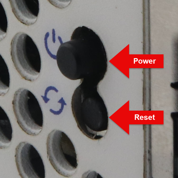
Close-up angle of the power and reset buttons
The power and reset buttons are depicted in Close-up angle of the power and reset buttons to clearly distinguish which is power (protruding) and which is reset (recessed).
Networking Ports
The sections on the rear of the device numbered 7 and 8 in Rear side view of the Netgate 5200 Firewall Appliance contain the network interfaces. These ports are labeled 1 through 5 on the device.
Label |
Assigned Name |
Device Name |
Type |
Speed |
|---|---|---|---|---|
1 |
WAN |
igc2 |
RJ-45 |
2.5 Gbps |
2 |
LAN |
igc1 |
RJ-45 |
2.5 Gbps |
3 |
OPT1 |
igc0 |
RJ-45 |
2.5 Gbps |
4 |
OPT2 |
igc3 |
RJ-45 |
2.5 Gbps |
5 |
OPT3 |
igb0 |
RJ-45 |
1 Gbps |
Note
The igc(4) network interfaces on this device do not
implement fixed speed operation. These interfaces emulate a speed/duplex
choice by limiting the values offered during autonegotiation to the
speed/duplex value selected in the GUI.
When connecting different devices to these interfaces the peer should typically be set to autonegotiate, not to a specific speed or duplex value. The exception to this is if the peer interface has the same limitation, in which case both peers should select the same negotiation speed.
Rear Side
The rear of the device has power and related items.
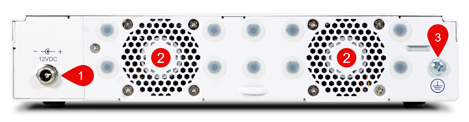
Rear side view of the Netgate 5200 Firewall Appliance
# |
Description |
Purpose |
|---|---|---|
1 |
Power Connector |
Supplying power to the appliance |
2 |
Exhaust Fans |
Expel hot air from the rear of the appliance |
3 |
Grounding Screw |
Screw for connecting to electrical ground |
- Power Connector (1)
The Power connector is 12VDC with threaded locking connector.
- Exhaust Fans (2)
The Netgate 5200 has active cooling. These two 40mm chassis fans pull airflow from the front of the appliance across the passive heatsink on the CPU, then expel that hot air out the rear.
- Grounding Screw (3)
This terminal allows the appliance chassis to be connected to a common ground, rack, or other supplemental ground to reduce electromagnetic interference.
Status LEDs
The Netgate 5200 has status LEDs to visually indicate the system status.
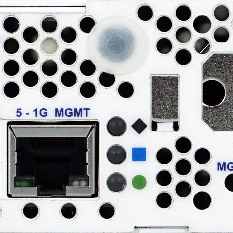
Status LEDs on the rear of the Netgate 5200 Firewall Appliance, to the right of the Networking Ports.
LED Patterns
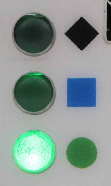
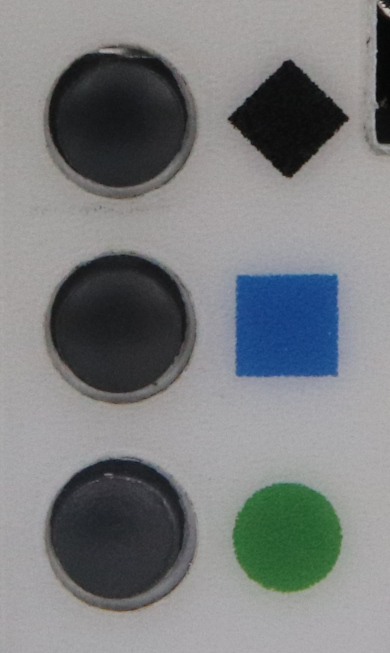
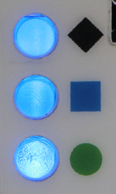
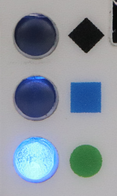
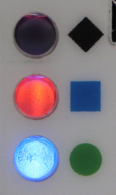
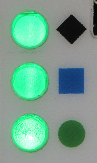
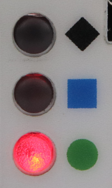
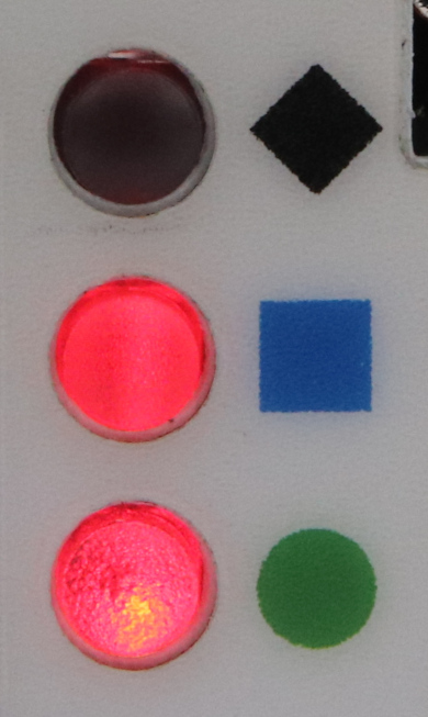
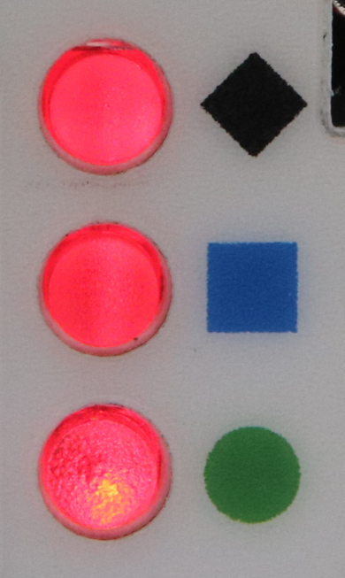
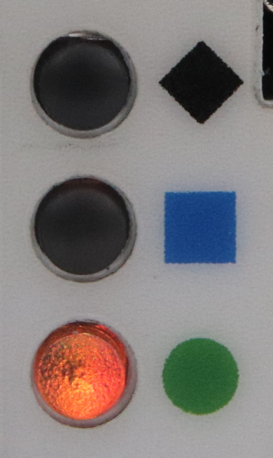
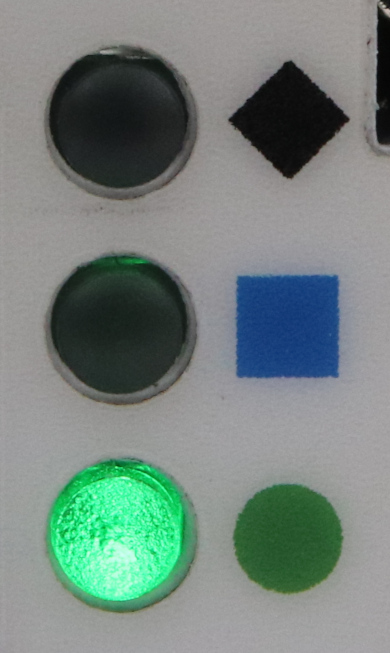
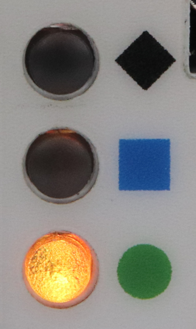
The LEDs on the device will light up and/or blink in one of the following patterns to indicate the system status:
LED States |
LED Patterns |
Description |
|---|---|---|
|
Circle Flashing Green |
Power On Self Test / Firmware Setup |
|
All Flashing Blue |
OS Boot in progress |
|
Circle Solid Blue |
Boot completed, ready for use |
|
Square Solid Amber |
Upgrade is available |
|
All Flashing Green |
Upgrade in progress |
|
Circle, Square, then Diamond Solid Red |
Triggering Factory Reset |
|
All Flashing Red |
Factory Reset in progress |
|
Circle Pulsing Orange |
In standby mode / OS halted |
|
Circle Pulsing Green |
Powering on from graceful standby |
|
Circle Solid Orange |
Powering on from hard standby |