Expansion Card Installation
The XG-7100 1U has a x4 PCIe expansion bus. By default, the expansion card riser and extender are not installed unless purchased separately with an expansion card.
Note
Although the PCIe expansion bus is x4, the extender can accommodate x4 or x8 expansion cards.
Some older extenders were x4 only.
Warning
Before proceeding:
Backup the configuration file.
Unplug the system for at least 60 seconds to ensure all phantom power has dissipated.
Anti-static protection must be used throughout this procedure.
Any hardware damage incurred during this procedure is not covered by the hardware warranty.
The XG-7100 PCIe Installation Kit from Netgate includes the components pictured below.
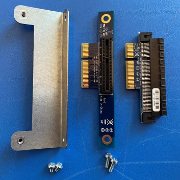
Bracket, Screws, Riser, and Extender
When installing an optional expansion card, first install the riser and extender using the riser mounting bracket. The instructions below are for installing an X710 expansion card, but other expansion cards are installed the same way.
Remove the seven (7) lid screws and remove the lid.
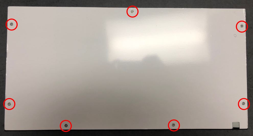
Lid Screws
Note
Some systems may only have six (6) lid screws.
Remove the faceplate by unscrewing the 4 black faceplate screws.
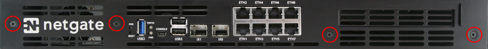
Remove the Faceplate
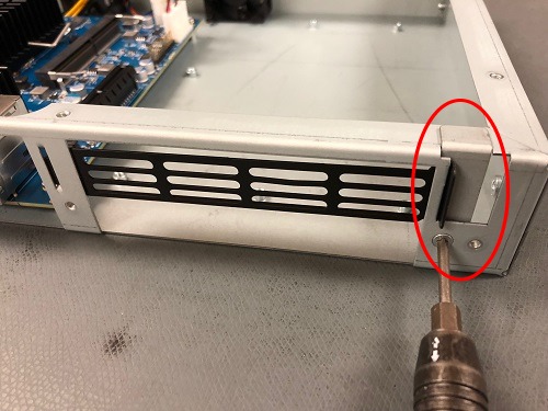
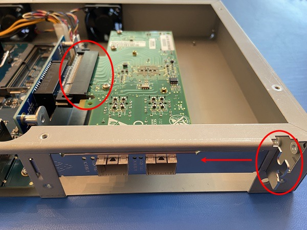
Remove the L-Bracket behind the faceplate blank by unscrewing 1U Lid screw (M3x0.5 6MM Long Flat Head).
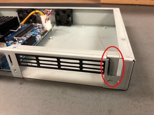
The L-Bracket and Screw
Note
Notice that the L-Bracket is behind the Faceplate Blank, locking it into place.
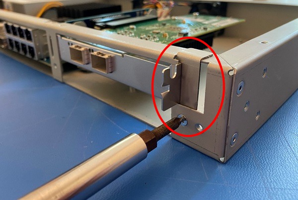
Remove the L-Bracket and Screw
Remove the faceplate blank.
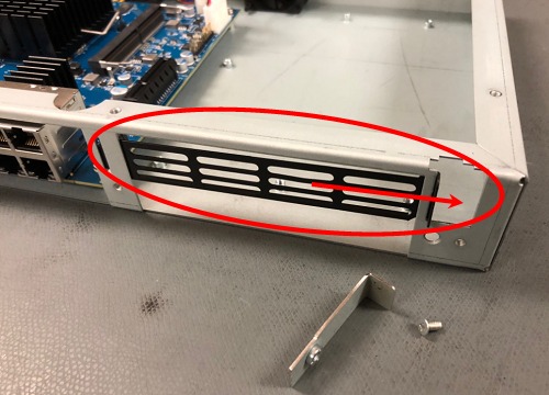
Remove the Faceplate Blank
Using Long Board Mount Screws, attach the riser card to the mounting bracket.
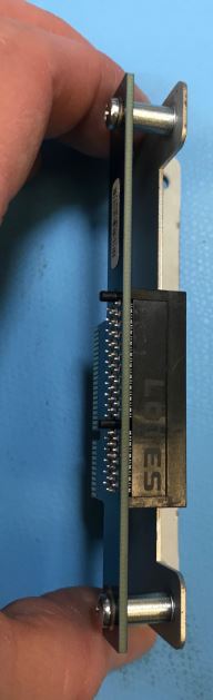
Attach Riser to Bracket
Line up the riser with the connector and insert the riser into the slot.
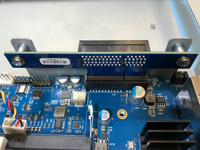
Align the Riser to the Connector and Insert
Attach the bracket to the chassis using Short Board Mount Screws.
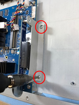
Attach the Bracket to the Chassis
Line up the extender and insert it into the riser.
Warning
The connection is keyed, and the riser will only go in one way. Do not force it.
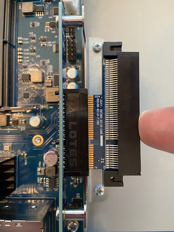
Line up the Extender with the Riser as shown
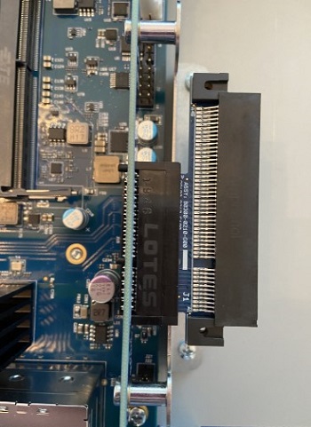
Extender seated into the Riser
Carefully align the expansion card with the extender.
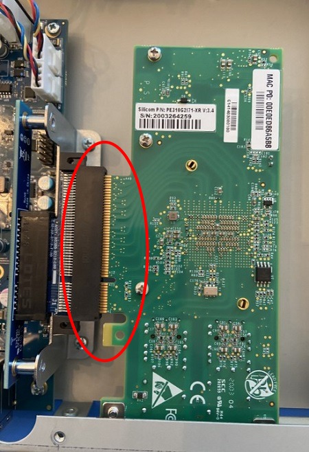
Align Expansion Card with Extender
Insert the Expansion Card fully into the extender.
Insert Expansion Card
Place the L-Bracket behind the expansion card and screw into place using a Lid Screw.
Secure the Expansion Card with the L-Bracket
Reattach the faceplate with 4 black faceplate screws.
Replace the lid.