Getting Started
The basic firewall configuration begins with connecting the Netgate® appliance to the Internet. Neither the modem nor the Netgate appliance should be powered on at this time.
Establishing a connection to an Internet Service Provider (ISP) starts with connecting one end of an Ethernet cable to the WAN port (shown in the Input and Output Ports section) of the Netgate appliance.
Warning
The default LAN subnet on the firewall is 192.168.1.0/24. The same subnet
cannot be used on both WAN and LAN, so if the subnet on the WAN side of
the firewall is also 192.168.1.0/24, disconnect the WAN interface
until the LAN interface has been renumbered to a different subnet.
The opposite end of the same Ethernet cable should be inserted in to the LAN port of the ISP-supplied modem. The modem provided by the ISP might have multiple LAN ports. If so, they are usually numbered. For the purpose of this installation, please select port 1.
The next step is to connect the LAN port (shown in the Input and Output Ports section) of the Netgate appliance to the computer which will be used to access the firewall console.
Connect one end of the second Ethernet cable to the LAN port (shown in the
Input and Output Ports section) of the Netgate appliance. Connect the other end to
the network connection on the computer. To access the GUI, the PC network
interface must be set to use DHCP, or have a static IP set in the
192.168.1.x subnet with a subnet mask of 255.255.255.0. Do not use
192.168.1.1, as this is the address of the firewall, and will cause an IP
conflict.
Initial Setup
The next step is to power up the modem and the firewall. Plug in the power supply to the power port (shown in the Input and Output Ports section).
Once the modem and Netgate appliance are powered up, the next step is to power up the computer.
Once the Netgate appliance is booted, the attached computer should receive a
192.168.1.x IP address via DHCP from the Netgate appliance.
Logging Into the Web Interface
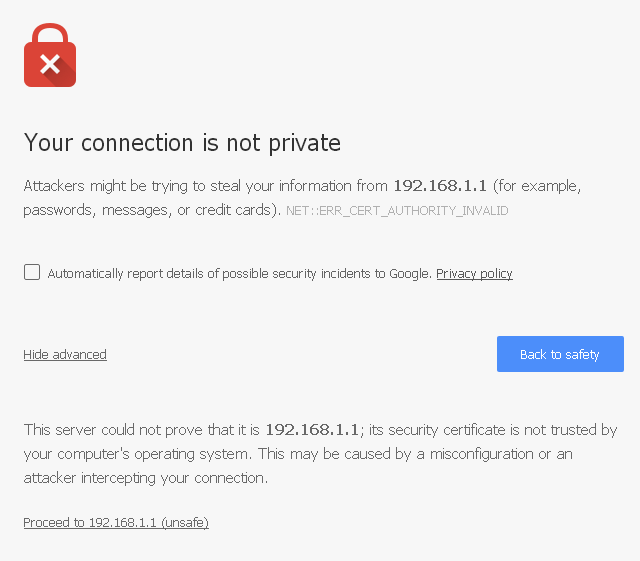
Browse to https://192.168.1.1 to access the web interface. In some instances, the browser may respond with a message indicating a problem with website security. Below is a typical example in Google Chrome. If this message or similar message is encountered, it is safe to proceed.
At the login page enter the default password and username:
- Username:
admin- Password:
pfsense
Click Login to continue
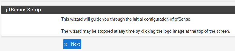
Wizard
Upon successful login, the GUI displays the following
Configuring Hostname, Domain Name and DNS Servers
Hostname
For Hostname, any desired name can be entered as it does not affect functionality of the firewall. Assigning a hostname to the firewall will allow clients to access the GUI by hostname as well as IP address.
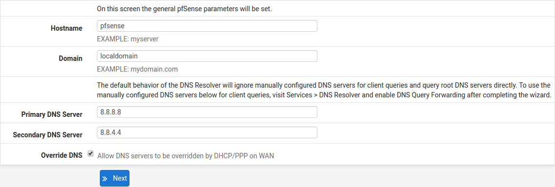
For the purposes of this guide, use pfsense for the hostname. The default
hostname, pfsense may be left unchanged.
Once saved in the configuration, the GUI may be accessed by entering http://pfsense as well as http://192.168.1.1
Domain
If an existing DNS domain is in use within the local network (such as a Microsoft Active Directory domain), use that domain here. This is the domain suffix assigned to DHCP clients, which should match the internal network.
For networks without any internal DNS domains, enter any desired domain name.
The default localdomain is used for the purposes of this tutorial.
DNS Servers
The DNS server fields can be left blank if the DNS Resolver will be left in the default non-forwarding mode. The settings may also be left blank if the WAN connection is using DHCP, PPTP or PPPoE types of Internet connections and the ISP automatically assigns DNS server IP addresses.
If using the DNS Resolver in forwarding mode or the DNS forwarder combined with a static IP address on WAN, DNS server IP addresses must be entered here for name resolution to function.
DNS servers can be specified here even if they differ from the servers assigned
by the ISP. Either enter the IP addresses provided by the ISP, or consider using
Google public DNS servers (8.8.8.8, 8.8.4.4). Google DNS servers are
used for the purpose of this tutorial. Click Next after filling in the
fields as appropriate.
Time Server Configuration
Time Server Synchronization
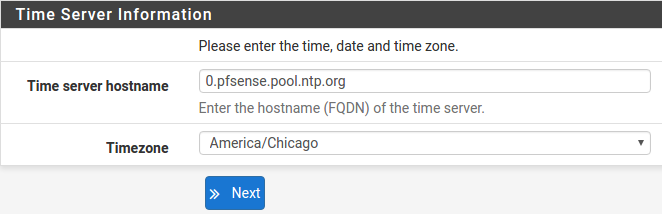
Setting time server synchronization is quite simple. The best practice is to use the default time server address, which will randomly select several NTP servers from a pool.
Setting Time Zone
Select an appropriate time zone for the location of the firewall. For purposes
of this manual, the Timezone setting will be set to America/Chicago for US
Central time.
Configuring Wide Area Network (WAN) Type
The WAN interface type is the next to be configured. The IP address assigned to this section becomes the Public IP address that this network will use to communicate with the Internet.
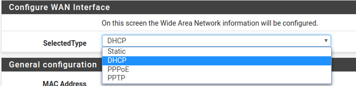
This depicts the four possible WAN interface types. Static, DHCP, PPPoE and PPTP. One must be selected from the drop-down list.
Further information from the ISP is required to proceed when selecting Static, PPPoE and PPTP such as login name and password or as with static addresses, an IP address, subnet mask and gateway address.
DHCP is the most common type of interface for home cable modems. One dynamic IP address is issued from the ISP DHCP server and will become the public IP address of the network behind this firewall. This address will change periodically at the discretion of the ISP. Select DHCP as shown and proceed to the next section.
MAC Address
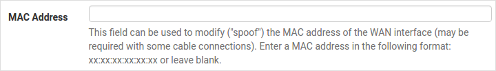
If replacing an existing firewall on an ISP that strictly controls MAC address changes, the WAN MAC address of the old firewall may be entered here, if it can be determined. This is typically unnecessary, but it can help avoid temporary issues involved in switching out firewalls, such as ARP caches, ISPs locking to single MAC addresses, etc.
If the MAC address of the old firewall cannot be located, the impact is most likely insignificant. Power cycle the ISP router and modem and the new MAC address will usually be able to get online. For some ISPs, it may be necessary to call them when switching devices, or an activation process may be required.
Configuring MTU and MSS
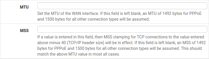
MTU or Maximum Transmission Unit determines the largest protocol data unit that can be passed onwards. A 1500-byte packet is the largest packet size allowed by Ethernet at the network layer and for the most part, the Internet so leaving this field blank allows the system to default to 1500-byte packets. PPPoE is slightly smaller at 1492-bytes. Leave this blank for a basic configuration.
Configuring DHCP Hostname
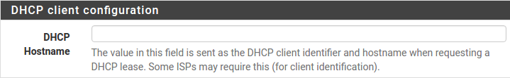
Some ISPs specifically require a DHCP Hostname entry. Unless the ISP requires the setting, leave it blank.
Configuring PPPoE and PPTP Interfaces
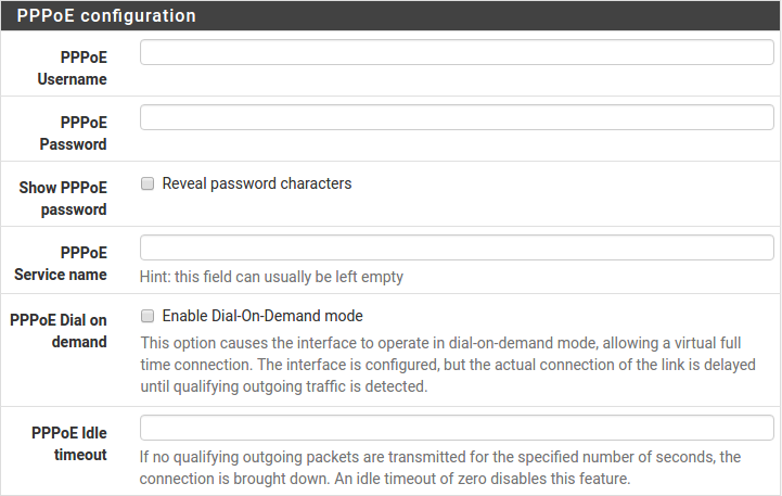
Information added in these sections is assigned by the ISP. Configure these settings as directed by the ISP
Block Private Networks and Bogons
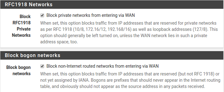
When enabled, the firewall will block all private network traffic from entering the WAN interface.
Private addresses are reserved for use on internal LANs and blocked from outside traffic, so these address ranges may be reused by all private networks.
The following inbound address Ranges are blocked by this firewall rule:
10.0.0.1to10.255.255.255172.16.0.1to172.31.255.254192.168.0.1to192.168.255.254127.0.0.0/8100.64.0.0/10fc00::/7
Bogons are public IP addresses that have not yet been allocated, so they may typically also be safely blocked as they should not be in active use.
Check Block RFC1918 Private Networks and Block Bogon Networks.
Click Next to continue.
Configuring LAN IP Address & Subnet Mask
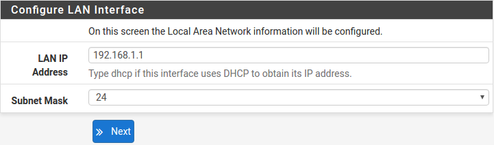
A static IP address of 192.168.1.1 and a subnet mask (CIDR) of 24 was
chosen for this installation. If there are no plans to connect this network to
any other network via VPN, the 192.168.1.x default is sufficient.
Click Next to continue.
Note
If a Virtual Private Network (VPN) is configured to remote locations, choose
a private IP address range more obscure than the very common
192.168.1.0/24. IP addresses within the 172.16.0.0/12 RFC1918 private
address block are the least frequently used.
The best practice is to select a block of addresses between 172.16.x.x
and 172.31.x.x for least likelihood of having VPN connectivity
difficulties. An example of a conflict would be If the local LAN is set to
192.168.1.x and a remote user is connected to a wireless hotspot using
192.168.1.x (very common), the remote client won’t be able to communicate
across the VPN to the local network.
Change Administrator Password
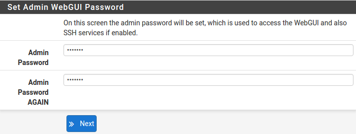
Select a new Administrator Password and enter it twice, then click Next to continue.
Save Changes
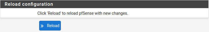
Click Reload to save configuration.
Basic Firewall Configured
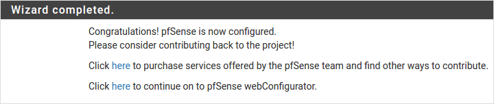
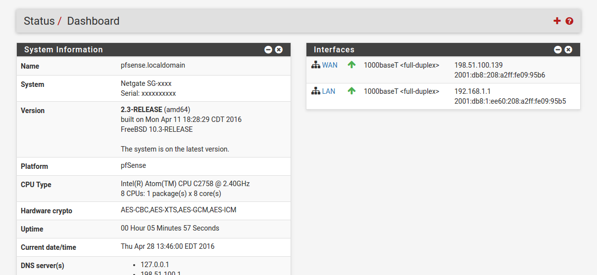
To proceed to the GUI, make the selection as highlighted. The browser will then display the Dashboard.
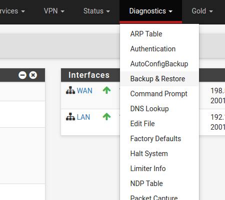
Backing Up and Restoring
At this point, basic LAN and WAN interface configuration is complete. Before proceeding, backup the firewall configuration. From the menu at the top of the page, browse to Diagnostics > Backup/Restore.
Click Download Configuration and save a copy of the firewall configuration.
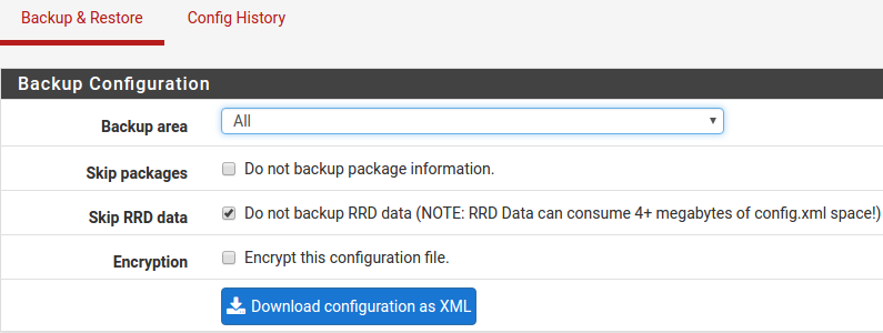
This configuration can be restored from the same screen by choosing the backup file under Restore configuration.
Connecting to the Console
There are times when accessing the console is required. Perhaps GUI console access has been locked out, or the password has been lost or forgotten.
See also
- Connecting to the USB Console
Connect to the console. Cable is required.
Tip
To learn more about getting the most out of a Netgate appliance, sign up for a pfSense Plus Software Training course or browse the extensive Resource Library.