Tip
This is the documentation for the v21.03 version. Looking for the documentation of the latest version? Have a look here.
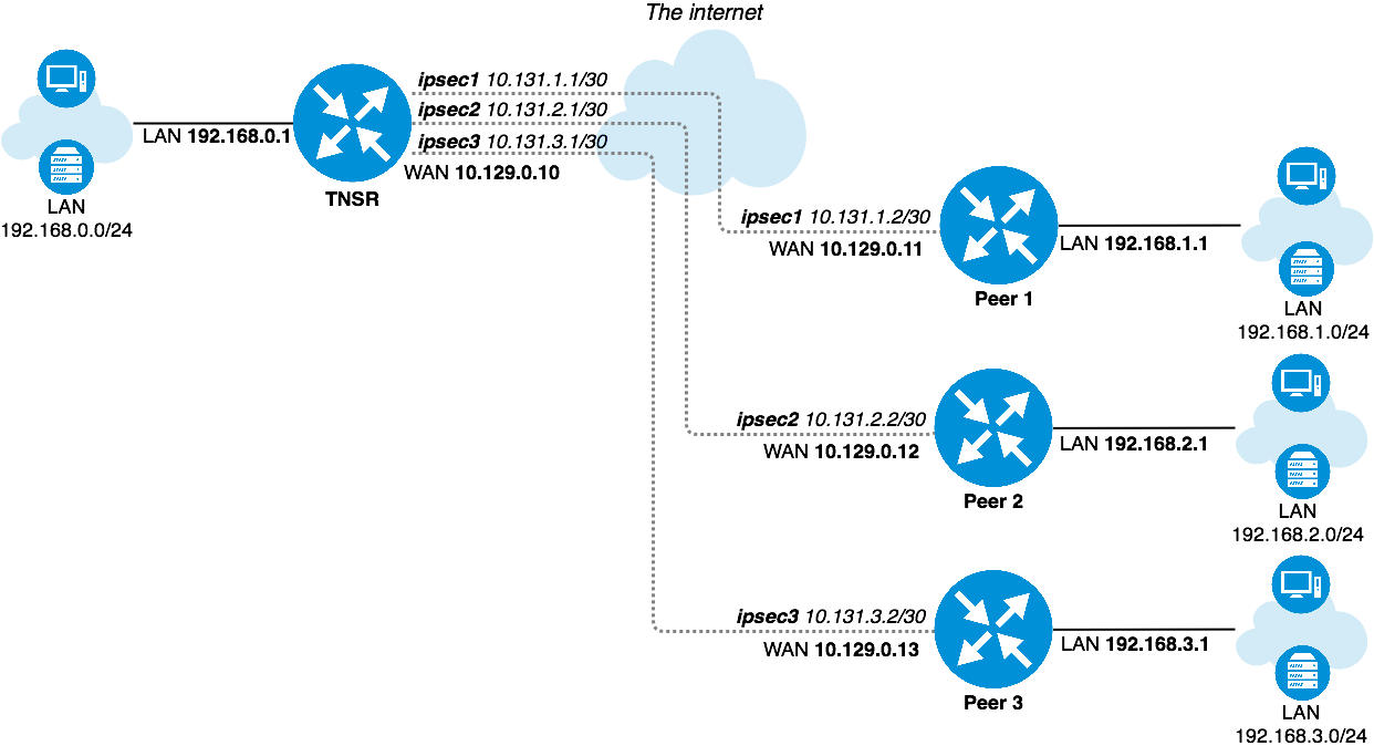
TNSR IPsec Hub for pfSense
Current scenario:
HQ (hub) with 3 branch (spoke) sites, with secure interconnection between thier local networks. One of the branch routers is assumed to be BGP capable. Internet access for one of the sites should be provided through the hub node.
Tip
This recipe does not contain configuration examples for IPsec cryptographic acceleration, which can greatly improve the efficiency and performance of IPsec tunnels. The availability of acceleration varies by hardware, so the specifics of acceleration configuration must be customized to the target environment.
For more information, see IPsec Cryptographic Acceleration
Input Data
The information in this section defines the local configuration which is covered in this recipe. These input values can be substituted by the actual corresponding values for a real-world implementation.
Scenario Topology
TNSR IPsec Hub
TNSR and Peer Network Configuration
Item |
Value |
|---|---|
VRF Name |
default |
LAN Interface |
GigabitEthernetb/0/0 |
LAN Network |
192.168.0.0/24 |
LAN IP Address static |
192.168.0.1/24 |
WAN Interface |
GigabitEthernet13/0/0 |
WAN IP Address DHCP |
10.129.0.10/24 |
IPsec VTI Peer 1 IP Address |
10.131.1.1/30 |
IPsec VTI Peer 2 IP Address |
10.131.2.1/30 |
IPsec VTI Peer 3 IP Address |
10.131.3.1/30 |
Item |
Value |
|---|---|
LAN Interface |
LAN |
LAN Network |
192.168.1.0/24 |
LAN IP Address static |
192.168.1.1/24 |
WAN Interface |
WAN |
WAN IP Address DHCP |
10.129.0.11/24 |
IPsec VTI TNSR IP Address |
10.131.1.2/30 |
Item |
Value |
|---|---|
LAN Interface |
LAN |
LAN Network |
192.168.2.0/24 |
LAN IP Address static |
192.168.2.1/24 |
WAN Interface |
WAN |
WAN IP Address DHCP |
10.129.0.12/24 |
IPsec VTI TNSR IP Address |
10.131.2.2/30 |
Item |
Value |
|---|---|
LAN Interface |
LAN |
LAN Network |
192.168.3.0/24 |
LAN IP Address static |
192.168.3.1/24 |
WAN Interface |
WAN |
WAN IP Address DHCP |
10.129.0.13/24 |
IPsec VTI TNSR IP Address |
10.131.3.2/30 |
TNSR and Peer IPsec Configuration
General IPsec settings are the same for every node.
Item |
Value |
|---|---|
Network Interface |
WAN Interface |
IKE type |
IKEv2 |
Authentication method |
PSK |
Pre-Share Key |
01234567 |
Local identifier |
WAN IP Address |
Remote identifier |
Remote WAN IP Address |
Encryption |
AES-128-CBC |
Hash |
SHA1 |
DH group |
14 (2048 bit modulus) |
Lifetime |
28800 |
Item |
Value |
|---|---|
Mode |
Routed IPsec (VTI) |
Protocol |
ESP |
Encryption |
AES-128-CBC |
Hash |
SHA1 |
PFS group |
14 (2048) |
Lifetime |
3600 |
Setup Details
Initial setup
It is assumed that devices have generic default setup, do not have any existing configuration errors, and are ready to be configured.
Note
In this scenario every device obtains its own static IP address on its WAN interface from an external lab gateway which is not a part of the considered scenario.
TNSR Setup
LAN settings
Setup LAN interface with static IP address:
tnsr tnsr# configure
tnsr tnsr(config)# interface GigabitEthernetb/0/0
tnsr tnsr(config-interface)# description LAN
tnsr tnsr(config-interface)# ip address 192.168.0.1/24
tnsr tnsr(config-interface)# enable
tnsr tnsr(config-interface)# exit
tnsr tnsr(config)# exit
WAN settings
Setup WAN interface for obtaining IP address via DHCP:
tnsr tnsr# configure
tnsr tnsr(config)# interface GigabitEthernet13/0/0
tnsr tnsr(config-interface)# description WAN
tnsr tnsr(config-interface)# dhcp client ipv4 hostname tnsr
tnsr tnsr(config-interface)# enable
tnsr tnsr(config-interface)# exit
tnsr tnsr(config)# exit
DHCP server
Setup DHCP server on LAN interface with following settings:
Item |
Value |
|---|---|
DHCP IP address pool |
192.168.0.100 to 192.168.0.199 |
Default gateway |
TNSR LAN IP address |
DNS |
8.8.8.8 and 1.1.1.1 |
tnsr tnsr# configure
tnsr tnsr(config)# dhcp4 server
tnsr tnsr(config-kea-dhcp4)# description LAN DHCP
tnsr tnsr(config-kea-dhcp4)# interface listen GigabitEthernetb/0/0
tnsr tnsr(config-kea-dhcp4)# lease lfc-interval 3600
tnsr tnsr(config-kea-dhcp4)# subnet 192.168.0.0/24
tnsr tnsr(config-kea-subnet4)# interface GigabitEthernetb/0/0
tnsr tnsr(config-kea-subnet4)# pool 192.168.0.100-192.168.0.199
tnsr tnsr(config-kea-subnet4-pool)# exit
tnsr tnsr(config-kea-subnet4)# option routers
tnsr tnsr(config-kea-subnet4-opt)# data 192.168.0.1
tnsr tnsr(config-kea-subnet4-opt)# exit
tnsr tnsr(config-kea-subnet4)# option domain-name-servers
tnsr tnsr(config-kea-subnet4-opt)# data 8.8.8.8, 1.1.1.1
tnsr tnsr(config-kea-subnet4-opt)# exit
tnsr tnsr(config-kea-subnet4)# exit
tnsr tnsr(config-kea-dhcp4)# exit
tnsr tnsr(config)# dhcp4 enable
tnsr tnsr(config)# exit
NAT
tnsr tnsr# configure
tnsr tnsr(config)# nat global-options nat44 forwarding true
tnsr tnsr(config)# nat global-options nat44 endpoint-dependent true
tnsr tnsr(config)# nat global-options nat44 enabled true
tnsr tnsr(config)# nat pool interface GigabitEthernet13/0/0
tnsr tnsr(config)# interface GigabitEthernetb/0/0
tnsr tnsr(config-interface)# ip nat inside
tnsr tnsr(config-interface)# exit
tnsr tnsr(config)# interface GigabitEthernet13/0/0
tnsr tnsr(config-interface)# ip nat outside
tnsr tnsr(config-interface)# exit
tnsr tnsr(config)# exit
Peer 1 Basic Setup
LAN settings
Setup LAN interface with static IP address.
Navigate to Interfaces > LAN
Set IPv4 Configuration Type to Static IPv4
Set IPv4 Address to
192.168.1.1and mask as24Click Save
Click Apply Changes
WAN settings
Setup WAN interface for obtaining an IP address via DHCP. This could also be a static setup, following a similar form to the LAN settings above.
Navigate to Interfaces > WAN
Set IPv4 Configuration Type to DHCP
Click Save
Click Apply Changes
DHCP server
Setup DHCP server on LAN interface with following settings:
Item |
Value |
|---|---|
DHCP IP address pool |
192.168.1.100 to 192.168.1.199 |
Default gateway |
LAN IP address (pfSense Default) |
DNS |
LAN IP address (pfSense Default) |
Navigate to Services > DHCP Server, LAN tab
Set Range From as
192.168.1.100and To as192.168.1.199Click Save
Peer 2 Basic Setup
LAN settings
Setup LAN interface with static IP address.
Navigate to Interfaces > LAN
Set IPv4 Configuration Type to Static IPv4
Set IPv4 Address to
192.168.2.1and mask as24Click Save
Click Apply Changes
WAN settings
Setup WAN interface for obtaining an IP address via DHCP. This could also be a static setup, following a similar form to the LAN settings above.
Navigate to Interfaces > WAN
Set IPv4 Configuration Type to DHCP
Click Save
Click Apply Changes
DHCP server
Setup DHCP server on LAN interface with following settings:
Item |
Value |
|---|---|
DHCP IP address pool |
192.168.2.100 to 192.168.2.199 |
Default gateway |
LAN IP address (pfSense Default) |
DNS |
LAN IP address (pfSense Default) |
Navigate to Services > DHCP Server, LAN tab
Set Range From as
192.168.2.100and To as192.168.2.199Click Save
Peer 3 Basic Setup
LAN settings
Setup LAN interface with static IP address.
Navigate to Interfaces > LAN
Set IPv4 Configuration Type to Static IPv4
Set IPv4 Address to
192.168.3.1and mask as24Click Save
Click Apply Changes
WAN settings
Setup WAN interface for obtaining an IP address via DHCP. This could also be a static setup, following a similar form to the LAN settings above.
Navigate to Interfaces > WAN
Set IPv4 Configuration Type to DHCP
Click Save
Click Apply Changes
DHCP server
Setup DHCP server on LAN interface with following settings:
Item |
Value |
|---|---|
DHCP IP address pool |
192.168.3.100 to 192.168.3.199 |
Default gateway |
LAN IP address (pfSense Default) |
DNS |
LAN IP address (pfSense Default) |
Navigate to Services > DHCP Server, LAN tab
Set Range From as
192.168.3.100and To as192.168.3.199Click Save
Access between local and remote networks via IPsec
This section describes minimal IPsec and routing settings in order to obtain secure interconnectivity between LAN networks for every device.
This document assumes that devices have generic initial setup successfully completed and are able to reach each other via WAN network.
TNSR
IPsec Configuration
IPsec setup for each pfSense node
IPsec to Peer 1
Enter config state:
tnsr tnsr# configure
Creating IPsec instance with id 1:
tnsr tnsr(config)# ipsec tunnel 1
tnsr tnsr(config-ipsec-tunnel)# local-address 10.129.0.10
tnsr tnsr(config-ipsec-tunnel)# remote-address 10.129.0.11
tnsr tnsr(config-ipsec-tunnel)# crypto config-type ike
P1 encryption settings:
tnsr tnsr(config-ipsec-tunnel)# crypto ike
tnsr tnsr(config-ipsec-crypto-ike)# version 2
tnsr tnsr(config-ipsec-crypto-ike)# lifetime 28800
tnsr tnsr(config-ipsec-crypto-ike)# proposal 1
tnsr tnsr(config-ike-proposal)# encryption aes128
tnsr tnsr(config-ike-proposal)# integrity sha1
tnsr tnsr(config-ike-proposal)# group modp2048
tnsr tnsr(config-ike-proposal)# exit
Creating peer IDs:
tnsr tnsr(config-ipsec-crypto-ike)# identity local
tnsr tnsr(config-ike-identity)# type address
tnsr tnsr(config-ike-identity)# value 10.129.0.10
tnsr tnsr(config-ike-identity)# exit
tnsr tnsr(config-ipsec-crypto-ike)# identity remote
tnsr tnsr(config-ike-identity)# type address
tnsr tnsr(config-ike-identity)# value 10.129.0.11
tnsr tnsr(config-ike-identity)# exit
Authentication:
tnsr tnsr(config-ipsec-crypto-ike)# authentication local
tnsr tnsr(config-ike-authentication)# round 1
tnsr tnsr(config-ike-authentication-round)# type psk
tnsr tnsr(config-ike-authentication-round)# psk 01234567
tnsr tnsr(config-ike-authentication-round)# exit
tnsr tnsr(config-ike-authentication)# exit
tnsr tnsr(config-ipsec-crypto-ike)# authentication remote
tnsr tnsr(config-ike-authentication)# round 1
tnsr tnsr(config-ike-authentication-round)# type psk
tnsr tnsr(config-ike-authentication-round)# psk 01234567
tnsr tnsr(config-ike-authentication-round)# exit
tnsr tnsr(config-ike-authentication)# exit
P2 settings:
tnsr tnsr(config-ipsec-crypto-ike)# child 1
tnsr tnsr(config-ike-child)# lifetime 3600
tnsr tnsr(config-ike-child)# proposal 1
tnsr tnsr(config-ike-child-proposal)# encryption aes128
tnsr tnsr(config-ike-child-proposal)# integrity sha1
tnsr tnsr(config-ike-child-proposal)# group modp2048
tnsr tnsr(config-ike-child-proposal)# exit
tnsr tnsr(config-ike-child)# exit
tnsr tnsr(config-ipsec-crypto-ike)# exit
tnsr tnsr(config-ipsec-tunnel)# exit
Configuring tunnel interface
tnsr tnsr(config)# interface ipip1
tnsr tnsr(config-interface)# ip address 10.131.1.1/30
tnsr tnsr(config-interface)# mtu 1400
tnsr tnsr(config-interface)# enable
tnsr tnsr(config-interface)# exit
tnsr tnsr(config)# exit
IPsec to Peer 2
Enter config state:
tnsr tnsr# configure
Creating IPsec instance with id 2:
tnsr tnsr(config)# ipsec tunnel 2
tnsr tnsr(config-ipsec-tunnel)# local-address 10.129.0.10
tnsr tnsr(config-ipsec-tunnel)# remote-address 10.129.0.12
tnsr tnsr(config-ipsec-tunnel)# crypto config-type ike
P1 encryption settings:
tnsr tnsr(config-ipsec-tunnel)# crypto ike
tnsr tnsr(config-ipsec-crypto-ike)# version 2
tnsr tnsr(config-ipsec-crypto-ike)# lifetime 28800
tnsr tnsr(config-ipsec-crypto-ike)# proposal 1
tnsr tnsr(config-ike-proposal)# encryption aes128
tnsr tnsr(config-ike-proposal)# integrity sha1
tnsr tnsr(config-ike-proposal)# group modp2048
tnsr tnsr(config-ike-proposal)# exit
Creating peer ID’s:
tnsr tnsr(config-ipsec-crypto-ike)# identity local
tnsr tnsr(config-ike-identity)# type address
tnsr tnsr(config-ike-identity)# value 10.129.0.10
tnsr tnsr(config-ike-identity)# exit
tnsr tnsr(config-ipsec-crypto-ike)# identity remote
tnsr tnsr(config-ike-identity)# type address
tnsr tnsr(config-ike-identity)# value 10.129.0.12
tnsr tnsr(config-ike-identity)# exit
Authentication:
tnsr tnsr(config-ipsec-crypto-ike)# authentication local
tnsr tnsr(config-ike-authentication)# round 1
tnsr tnsr(config-ike-authentication-round)# type psk
tnsr tnsr(config-ike-authentication-round)# psk 01234567
tnsr tnsr(config-ike-authentication-round)# exit
tnsr tnsr(config-ike-authentication)# exit
tnsr tnsr(config-ipsec-crypto-ike)# authentication remote
tnsr tnsr(config-ike-authentication)# round 1
tnsr tnsr(config-ike-authentication-round)# type psk
tnsr tnsr(config-ike-authentication-round)# psk 01234567
tnsr tnsr(config-ike-authentication-round)# exit
tnsr tnsr(config-ike-authentication)# exit
P2 settings:
tnsr tnsr(config-ipsec-crypto-ike)# child 1
tnsr tnsr(config-ike-child)# lifetime 3600
tnsr tnsr(config-ike-child)# proposal 1
tnsr tnsr(config-ike-child-proposal)# encryption aes128
tnsr tnsr(config-ike-child-proposal)# integrity sha1
tnsr tnsr(config-ike-child-proposal)# group modp2048
tnsr tnsr(config-ike-child-proposal)# exit
tnsr tnsr(config-ike-child)# exit
tnsr tnsr(config-ipsec-crypto-ike)# exit
tnsr tnsr(config-ipsec-tunnel)# exit
Configuring tunnel interface:
tnsr tnsr(config)# interface ipip2
tnsr tnsr(config-interface)# ip address 10.131.2.1/30
tnsr tnsr(config-interface)# mtu 1400
tnsr tnsr(config-interface)# enable
tnsr tnsr(config-interface)# exit
tnsr tnsr(config)# exit
IPsec to Peer 3
Enter config state:
tnsr tnsr# configure
Creating IPsec instance with id 3:
tnsr tnsr(config)# ipsec tunnel 3
tnsr tnsr(config-ipsec-tunnel)# local-address 10.129.0.10
tnsr tnsr(config-ipsec-tunnel)# remote-address 10.129.0.13
tnsr tnsr(config-ipsec-tunnel)# crypto config-type ike
P1 encryption settings:
tnsr tnsr(config-ipsec-tunnel)# crypto ike
tnsr tnsr(config-ipsec-crypto-ike)# version 2
tnsr tnsr(config-ipsec-crypto-ike)# lifetime 28800
tnsr tnsr(config-ipsec-crypto-ike)# proposal 1
tnsr tnsr(config-ike-proposal)# encryption aes128
tnsr tnsr(config-ike-proposal)# integrity sha1
tnsr tnsr(config-ike-proposal)# group modp2048
tnsr tnsr(config-ike-proposal)# exit
Creating peer ID’s:
tnsr tnsr(config-ipsec-crypto-ike)# identity local
tnsr tnsr(config-ike-identity)# type address
tnsr tnsr(config-ike-identity)# value 10.129.0.10
tnsr tnsr(config-ike-identity)# exit
tnsr tnsr(config-ipsec-crypto-ike)# identity remote
tnsr tnsr(config-ike-identity)# type address
tnsr tnsr(config-ike-identity)# value 10.129.0.13
tnsr tnsr(config-ike-identity)# exit
Authentication:
tnsr tnsr(config-ipsec-crypto-ike)# authentication local
tnsr tnsr(config-ike-authentication)# round 1
tnsr tnsr(config-ike-authentication-round)# type psk
tnsr tnsr(config-ike-authentication-round)# psk 01234567
tnsr tnsr(config-ike-authentication-round)# exit
tnsr tnsr(config-ike-authentication)# exit
tnsr tnsr(config-ipsec-crypto-ike)# authentication remote
tnsr tnsr(config-ike-authentication)# round 1
tnsr tnsr(config-ike-authentication-round)# type psk
tnsr tnsr(config-ike-authentication-round)# psk 01234567
tnsr tnsr(config-ike-authentication-round)# exit
tnsr tnsr(config-ike-authentication)# exit
P2 settings:
tnsr tnsr(config-ipsec-crypto-ike)# child 1
tnsr tnsr(config-ike-child)# lifetime 3600
tnsr tnsr(config-ike-child)# proposal 1
tnsr tnsr(config-ike-child-proposal)# encryption aes128
tnsr tnsr(config-ike-child-proposal)# integrity sha1
tnsr tnsr(config-ike-child-proposal)# group modp2048
tnsr tnsr(config-ike-child-proposal)# exit
tnsr tnsr(config-ike-child)# exit
tnsr tnsr(config-ipsec-crypto-ike)# exit
tnsr tnsr(config-ipsec-tunnel)# exit
Configuring tunnel interface:
tnsr tnsr(config)# interface ipip3
tnsr tnsr(config-interface)# ip address 10.131.3.1/30
tnsr tnsr(config-interface)# mtu 1400
tnsr tnsr(config-interface)# enable
tnsr tnsr(config-interface)# exit
tnsr tnsr(config)# exit
Routing
This section describes routing setup. This scenario assumes one of the pfSense IPsec peers, Peer 1, uses a dynamic routing protocol (BGP) and the remaining two IPsec peers use static routing.
Peer 1 BGP Routing
Enter config state:
tnsr tnsr# configure
Defining redistributed networks, peer 2 and 3:
tnsr tnsr(config)# route dynamic prefix-list VPN-ROUTES
tnsr tnsr(config-prefix-list)# sequence 1 permit 192.168.2.0/23 le 24
tnsr tnsr(config-prefix-list)# exit
tnsr tnsr(config)# route dynamic route-map VPN-ROUTES-MAP
tnsr tnsr(config-route-map)# sequence 1
tnsr tnsr(config-route-map-rule)# policy permit
tnsr tnsr(config-route-map-rule)# match ip address prefix-list VPN-ROUTES
tnsr tnsr(config-route-map-rule)# exit
tnsr tnsr(config-route-map)# exit
Setup BGP instance:
tnsr tnsr(config)# route dynamic bgp
tnsr tnsr(config-frr-bgp)# server vrf default
tnsr tnsr(config-bgp)# as-number 65000
tnsr tnsr(config-bgp)# router-id 192.168.0.1
Defining neighbor:
tnsr tnsr(config-bgp)# neighbor 10.131.1.2
tnsr tnsr(config-bgp-neighbor)# remote-as 65001
tnsr tnsr(config-bgp-neighbor)# enable
tnsr tnsr(config-bgp-neighbor)# exit
Setup peer in certain address-family space:
tnsr tnsr(config-bgp)# address-family ipv4 unicast
tnsr tnsr(config-bgp-ip4uni)# neighbor 10.131.1.2
tnsr tnsr(config-bgp-ip4uni-nbr)# activate
tnsr tnsr(config-bgp-ip4uni-nbr)# exit
Defining local network in certain address-family space:
tnsr tnsr(config-bgp-ip4uni)# network 192.168.0.0/24
Defining redistributed networks
tnsr tnsr(config-bgp-ip4uni)# redistribute kernel route-map VPN-ROUTES-MAP
tnsr tnsr(config-bgp-ip4uni)# exit
tnsr tnsr(config-bgp)# exit
Enabling BGP if one is not enabled:
tnsr tnsr(config-frr-bgp)# enable
tnsr tnsr(config-frr-bgp)# exit
Better to restart service in order to be sure changes applied effectively:
tnsr tnsr(config)# service bgp restart
tnsr tnsr(config)# exit
Peer 2 Static Routing
tnsr tnsr# configure
tnsr tnsr(config)# route table ipv4-VRF:0
tnsr tnsr(config-route-table)# route 192.168.2.0/24
tnsr tnsr(config-rttbl4-next-hop)# next-hop 0 via 10.131.2.2
tnsr tnsr(config-rttbl4-next-hop)# exit
tnsr tnsr(config-route-table)# exit
tnsr tnsr(config)# exit
Peer 3 Static Routing
tnsr tnsr# configure
tnsr tnsr(config)# route table ipv4-VRF:0
tnsr tnsr(config-route-table)# route 192.168.3.0/24
tnsr tnsr(config-rttbl4-next-hop)# next-hop 0 via 10.131.3.2
tnsr tnsr(config-rttbl4-next-hop)# exit
tnsr tnsr(config-route-table)# exit
tnsr tnsr(config)# exit
Peer 1 Setup
IPsec Settings
Phase 1
Navigate to VPN > IPsec
Click Add P1
Set Key Exchange version to IKEv2
Set Internet Protocol to IPv4
Set Interface to WAN
Set Remote Gateway to
10.129.0.10Set Authentication Method to Mutual PSK
Set My identifier to My IP address
Set Peer identifier to Peer IP address
Set Pre-Shared Key to
01234567Set Encryption:
Algorithm to AES
Key length to 128 bit
Hash to SHA1
DH Group to 14 (2048 bit)
Set Lifetime as
28800Click Save
Phase 2
On the newly created Phase 1 entry, click Show Phase 2 Entries
Click Add P2
Set Mode to Routed (VTI)
Set Local Network to
10.131.2.2and mask30Set Remote Network to
10.131.2.1Set Protocol to ESP
Set Encryption Algorithms to AES and 128 bit
Uncheck all other Encryption Algorithms entries
Set Hash Algorithms to SHA1
Uncheck all other Hash Algorithms entries
Set PFS key group to 14 (2048 bit)
Set Lifetime as
3600Click Save
Click Apply Changes
Interface
Navigate to Interfaces > Interface Assignments
From the Available network ports list, choose ipsecNNNN (IPsec VTI) (The ID number will vary)
Click Add
Note the newly created interface name, such as OPTX
Navigate to Interfaces > OPTX
Check Enable
Click Save
Click Apply Changes
Routing
Navigate to System > Package Manager and install the FRR package
Browse to Services > FRR Global/Zebra
Check Enable FRR
Set Master Password to any value
Note
This is a requirement for the zebra management daemon to run, this password is not used by clients.
Check Enable logging
Set Router ID to
192.168.1.1In this case, it is the LAN interface IP address, assuming it will be always be available for routing between LAN subnets.
Click Save
Navigate to the [BGP] tab
Check Enable BGP Routing
Check Log Adjacency Changes
Set Local AS to
65001Set Router ID to
192.168.1.1Set Networks to Distribute to
192.168.1.0/24Navigate to the Neighbors tab
Click Add
Set Name/Address to
10.131.1.1(TNSR VTI interface IP address)Set Remote AS to
65000Click Save
At this point, routes to 192.168.0.0/24, 192.168.2.0/24, and
192.168.3.0/24 will be learned by BGP and installed in the routing table. If
it is not so, check Status > FRR on the BGP tab. That page contains
useful BGP troubleshooting information. Additionally, check the routing log at
Status > System Logs on the Routing tab under System.
Firewall
To allow connections into the local LAN from remote IPsec sites, create necessary pass rules under Firewall > Rules on the IPsec tab. These rules would have a Source set to the remote LAN or whichever network is the source of the traffic to allow.
For simplicity, this example has a rule to pass IPv4 traffic from any source to any destination since the only IPsec interface traffic will be from 192.168.0.0/22.
NAT
TNSR will perform NAT for this peer, so outbound NAT is not necessary. It may be left at the default, which will not touch IPsec traffic, or outbound NAT may be disabled entirely which will also prevent LAN subnet traffic from exiting out the WAN unintentionally.
Peer 2 Setup
IPsec Settings
Phase 1
Navigate to VPN > IPsec
Click Add P1
Set Key Exchange version to IKEv2
Set Internet Protocol to IPv4
Set Interface to WAN
Set Remote Gateway to
10.129.0.10Set Authentication Method to Mutual PSK
Set My identifier to My IP address
Set Peer identifier to Peer IP address
Set Pre-Shared Key to
01234567Set Encryption:
Algorithm to AES
Key length to 128 bit
Hash to SHA1
DH Group to 14 (2048 bit)
Set Lifetime as
28800Click Save
Phase 2
On the newly created Phase 1 entry, click Show Phase 2 Entries
Click Add P2
Set Mode to Routed (VTI)
Set Local Network to
10.131.3.2and mask30Set Remote Network to
10.131.3.1Set Protocol to ESP
Set Encryption Algorithms to AES and 128 bit
Uncheck all other Encryption Algorithms entries
Set Hash Algorithms to SHA1
Uncheck all other Hash Algorithms entries
Set PFS key group to 14 (2048 bit)
Set Lifetime as
3600Click Save
Click Apply Changes
Interface
Navigate to Interfaces > Interface Assignments
From the Available network ports list, choose ipsecNNNN (IPsec VTI) (The ID number will vary)
Click Add
Note the newly created interface name, such as OPTX
Navigate to Interfaces > OPTX
Check Enable
Click Save
Click Apply Changes
Routing
Navigate to System > Routing, Static Routes tab
Click Add
Set Destination network to
192.168.0.0and mask23Set Gateway to the newly created VTI interface gateway, which has an address of
10.131.2.1Click Save
Click Add
Set Destination network to
192.168.3.0and mask24Set Gateway to the newly created VTI interface gateway, which has an address of
10.131.2.1Click Save
Click Apply Changes
Firewall
To allow connections into the local LAN from remote IPsec sites, create necessary pass rules under Firewall > Rules on the IPsec tab. These rules would have a Source set to the remote LAN or whichever network is the source of the traffic to allow.
For simplicity, this example has a rule to pass IPv4 traffic from any source to any destination since the only IPsec interface traffic will be from 192.168.0.0/22.
NAT
TNSR will perform NAT for this peer, so outbound NAT is not necessary. It may be left at the default, which will not touch IPsec traffic, or outbound NAT may be disabled entirely which will also prevent LAN subnet traffic from exiting out the WAN unintentionally.
Peer 3 Setup
IPsec Settings
Phase 1
Navigate to VPN > IPsec
Click Add P1
Set Key Exchange version to IKEv2
Set Internet Protocol to IPv4
Set Interface to WAN
Set Remote Gateway to
10.129.0.10Set Authentication Method to Mutual PSK
Set My identifier to My IP address
Set Peer identifier to Peer IP address
Set Pre-Shared Key to
01234567Set Encryption:
Algorithm to AES
Key length to 128 bit
Hash to SHA1
DH Group to 14 (2048 bit)
Set Lifetime as
28800Click Save
Phase 2
On the newly created Phase 1 entry, click Show Phase 2 Entries
Click Add P2
Set Mode to Routed (VTI)
Set Local Network to
10.131.4.2and mask30Set Remote Network to
10.131.4.1Set Protocol to ESP
Set Encryption Algorithms to AES and 128 bit
Uncheck all other Encryption Algorithms entries
Set Hash Algorithms to SHA1
Uncheck all other Hash Algorithms entries
Set PFS key group to 14 (2048 bit)
Set Lifetime as
3600Click Save
Click Apply Changes
Interface
Navigate to Interfaces > Interface Assignments
From the Available network ports list, choose ipsecNNNN (IPsec VTI) (The ID number will vary)
Click Add
Note the newly created interface name, such as OPTX
Navigate to Interfaces > OPTX
Check Enable
Click Save
Click Apply Changes
Routing
Navigate to System > Routing, Static Routes tab
Click Add
Set Destination network to
192.168.0.0and mask23Set Gateway to the newly created VTI interface gateway, which has an address of
10.131.3.1Click Save
Click Add
Set Destination network to
192.168.2.0and mask24Set Gateway to the newly created VTI interface gateway, which has an address of
10.131.3.1Click Save
Click Apply Changes
Firewall
To allow connections into the local LAN from remote IPsec sites, create necessary pass rules under Firewall > Rules on the IPsec tab. These rules would have a Source set to the remote LAN or whichever network is the source of the traffic to allow.
For simplicity, this example has a rule to pass IPv4 traffic from any source to any destination since the only IPsec interface traffic will be from 192.168.0.0/22.
NAT
TNSR will perform NAT for this peer, so outbound NAT is not necessary. It may be left at the default, which will not touch IPsec traffic, or outbound NAT may be disabled entirely which will also prevent LAN subnet traffic from exiting out the WAN unintentionally.
Access to the internet for remote network
This section describes minimal routing and NAT settings which provide access to the Internet for one of the remote networks. In current case this is Peer 1 that exchanges routing information with TNSR via BGP.
This document assumes that devices have IPsec setup successfully completed, able to reach each other via IPsec tunnel using path information from the dynamic routing protocol.
TNSR
NAT/PAT
Setup NAT for remote network, in this case PAT is used.
Note
Defining NAT inside interface for internet traffic sourced from Peer 1. Outside interface and PAT were defined earlier.
tnsr tnsr# configure
tnsr tnsr(config)# interface ipip1
tnsr tnsr(config-interface)# ip nat inside
tnsr tnsr(config-interface)# exit
Peer 1 Policy Route
Routing
Setup access to the internet via IPsec VTI interface with a policy-based routing rule.
Navigate to Firewall > Rules
Create (or modify existing default pass ipv4 LAN any) rule:
Set Address Family to IPv4
Set Protocol to ANY
Set Source to LAN net
Set Destination to ANY
Click Display Advanced
Set Gateway to
<IPsec interface name>_VTIV4Click Save
Note
VTI on pfSense does not support reply-to. Despite this policy
routing rule on Peer1 which covers all traffic, there must also be kernel
routes to remote LANs for the return traffic to find the way back.