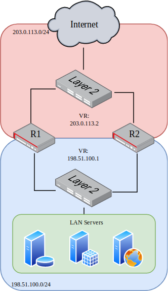
This example is a basic two-node VRRP cluster with an internal and
external VR address. This is a routed configuration with a statically
routed subnet used for the internal LAN.
In this example, the upstream ISP will deliver a routed subnet
(198.51.100.0/24) to the WAN-side VR address (203.0.113.2), and internal
clients will use the LAN-side VR address (198.51.100.1) as their gateway.
Interface tracking is included in the example to protect against a single
failure of either WAN or LAN.
See also
See VRRP Configuration for more information on how the commands in the
example function.
This information is for the secondary node, which in this example is called R2.
Note that the interface addresses are different from R1, but the same VR address
is used.
The configuration commands in this section show how the settings from the table
above are applied to each node. Some additional VRRP settings are shown in the
commands but not the tables, but they are using the default values, shown for
emphasis.
First, set the R1 interface names:
r1 tnsr(config)# dataplane dpdk dev 0000:06:00.0 network name WANr1 tnsr(config)# dataplane dpdk dev 0000:06:00.1 network name LANr1 tnsr(config)# service dataplane restart
r2 tnsr(config)# dataplane dpdk dev 0000:06:00.0 network name WANr2 tnsr(config)# dataplane dpdk dev 0000:06:00.1 network name LANr2 tnsr(config)# service dataplane restart