Input and Output Ports
Front Panel
The front panel of the Netgate 8300 contains several items of interest for connecting to and managing the device.
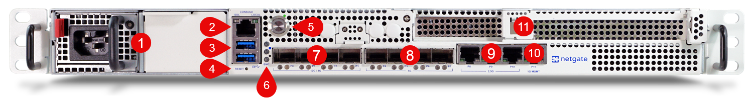
Front view of the Netgate 8300 Security Gateway with key items numbered
The items below are marked with numbers on figure Front view of the Netgate 8300 Security Gateway with key items numbered:
Item |
Description |
|---|---|
1 |
Power Supply Unit (PSU) Bays |
2 |
Serial Console (RJ45) |
3 |
2x USB 3.0 Port |
4 |
Reset Button |
5 |
ACPI Power Button - Graceful shutdown, hard power off (Hold 10s), power on |
6 |
|
7 |
10G/1G SFP+ Networking Ports |
8 |
1G SFP Networking Ports |
9 |
2.5G RJ45 Networking Ports |
10 |
1G IPMI Management Port (P11, Intelligent Platform Management Interface (IPMI)) |
11 |
Add-on Expansion Card Slots |
- Power Supply Unit (PSU) Bays (1)
The chassis contains two power supply unit bays located on the far left of the front side. The PSUs are hot swappable and the unit can operate with one or both PSUs connected to line power.
The Netgate 8300 BASE unit ships with one power supply, the Netgate 8300 MAX unit ships with dual power supplies. Additional power supplies are available. A second PSU can be added to the BASE model later by removing the blank panel cover.
Each PSU is 500W with 110V/240V AC input. It contains a standard IEC320-C16 (3-pin) power receptacle which accepts a standard IEC320-C15 power plug.
- Serial Console Port (2)
Clients can access the serial console using the RJ45 “Cisco” style console port with a separate cable and USB serial adapter or client hardware port.
Note
The RJ45 Serial Console port is only for use with the Serial Console. It cannot be used for any other purpose.
- 2x USB 3.0 Ports (3)
USB ports on the device can be used for a variety of purposes.
The primary use for the USB ports is to install or reinstall the operating system on the device. Beyond that, any purposes are left to administrators to configure and utilize.
- Reset Button (4)
The Reset Button acts as a standard hardware reset button and immediately resets the hardware when pressed.
- ACPI Power Button (5)
The large round lighted Power Button behaves the same as a typical ACPI power button.
If the device is powered on and running, pressing the button immediately performs a graceful shutdown and the system enters a standby state.
If the system is in a powered off or standby state, pressing the power button immediately powers on the device and starts the boot process.
If the system is unresponsive, holding in the power button for 10 seconds will forcefully power off the device. Press the power button again to turn it back on.
- Status LEDs (6)
The status LEDs, including the backlight on the power button, indicate various status information for the device. The power button LED and the first two LEDs from top to bottom are for OS status, while the bottom LED is for the status of the baseboard management controller (BMC).
See Status LEDs for information on interpreting the meaning of different LED states.
- 10G/1G SFP+ Networking Ports (7)
This group of four ports labeled P0-P3 are 10G/1G SFP+ Networking Ports.
- 1G SFP Networking Ports (8)
This group of four ports labeled P4-P7 are 1G SFP Networking Ports.
- 2.5G RJ45 Networking Ports (9)
This group of three ports labeled P8-P10 are 2.5G RJ45 Networking Ports.
- 1G IPMI Management Port (10)
The rightmost RJ45 port labeled P11 is the 1G MGMT port dedicated to IPMI. See Intelligent Platform Management Interface (IPMI) for details on how to access IPMI.
Note
This dedicated IPMI management port is not visible to or usable by the operating system.
- Add-on Expansion Card Slots (11)
These are expansion slots and covers which may house additional add-on cards such as for network interfaces. See Add-On Expansion Card Installation for installation information.
There are two available expansion slots:
1x PCIe 3.0 x8 LP (Low Profile) slot compatible with half-length low profile cards.
This slot has a PCIe-LP connector which is PCIe x16 but only wired for PCIe x8. While the slot is compatible with PCIe x16 half-length cards, only 8 lanes function.
1x PCIe 4.0 x16 slot compatible with full-height three-quarter length cards.
This x16 PCIe slot can supply a maximum of 75W directly.
Note
The power draw of standard 25-100 Gbit/s network interface cards will NOT exceed the standard 75W slot rating.
Networking Ports
The sections on the front of the device numbered 7, 8, and 9 in Front view of the Netgate 8300 Security Gateway with key items numbered contain the network interfaces. These ports are labeled P0 through P10 on the device and are grouped by speed.
Label |
Bus Address |
Linux Label |
TNSR Label |
Port Type |
Port Speed |
|---|---|---|---|---|---|
P0 |
0000:f4:00.0 |
eno2 |
TwentyFiveGigabitEthernetf4/0/0 |
SFP+ |
10 Gbps/1 Gbps |
P1 |
0000:f4:00.1 |
eno3 |
TwentyFiveGigabitEthernetf4/0/1 |
SFP+ |
10 Gbps/1 Gbps |
P2 |
0000:f4:00.2 |
eno4 |
TwentyFiveGigabitEthernetf4/0/2 |
SFP+ |
10 Gbps/1 Gbps |
P3 |
0000:f4:00.3 |
eno5 |
TwentyFiveGigabitEthernetf4/0/3 |
SFP+ |
10 Gbps/1 Gbps |
P4 |
0000:f4:00.4 |
enp244s0f4 |
TwentyFiveGigabitEthernetf4/0/4 |
SFP |
1 Gbps |
P5 |
0000:f4:00.5 |
enp244s0f5 |
TwentyFiveGigabitEthernetf4/0/5 |
SFP |
1 Gbps |
P6 |
0000:f4:00.6 |
enp244s0f6 |
TwentyFiveGigabitEthernetf4/0/6 |
SFP |
1 Gbps |
P7 |
0000:f4:00.7 |
enp244s0f7 |
TwentyFiveGigabitEthernetf4/0/7 |
SFP |
1 Gbps |
P8 |
0000:0d:00.0 |
eno1 |
TwoDotFiveGigabitEthernetd/0/0 |
RJ45 |
2.5 Gbps |
P9 |
0000:0b:00.0 |
ens9 |
TwoDotFiveGigabitEthernetb/0/0 |
RJ45 |
2.5 Gbps |
P10 |
0000:09:00.0 |
ens8 |
TwoDotFiveGigabitEthernet9/0/0 |
RJ45 |
2.5 Gbps |
Networking Ports with Add-on Cards
There are two add-on expansion card slots on the Netgate 8300 device, and they can both be populated with network cards, for a total of either two or four additional network ports.
Note
When two add-on cards are present the device probes and numbers the card on the left side first.
The following table shows interface information for a Netgate 8300 containing an E810-XXV card with 2x 25 Gbit/s ports in the x8 half height slot and an E810-C card with 2x 100 Gbit/s ports in the x16 full height slot.
Bus Address |
Linux Label |
TNSR Label |
Port Type |
Port Speed |
|---|---|---|---|---|
0000:03:00.0 |
enp3s0f0 |
TwentyFiveGigabitEthernet3/0/0 |
SFP28 |
25 Gbit/s |
0000:03:00.1 |
enp3s0f1 |
TwentyFiveGigabitEthernet3/0/1 |
SFP28 |
25 Gbit/s |
0000:15:00.0 |
ens6f0 |
HundredGigabitEthernet15/0/0 |
QSFP28 |
100 Gbit/s |
0000:15:00.1 |
ens6f1 |
HundredGigabitEthernet15/0/1 |
QSFP28 |
100 Gbit/s |
Compatible SFP/SFP+ Modules
In general, the modules most likely to be compatible with the SFP and SFP+ ports on the Netgate 8300 are Intel or Intel-compatible transceivers.
Table Known-Working SFP/SFP+ Modules contains a list of SFP and SFP+ modules reported working with the Netgate 8300 along with their known limitations.
Module |
Media |
Notes |
|---|---|---|
10GTek ASF-10G-T80 |
10GBase-T SFP+ 80m Copper RJ-45 CAT 6a/7 |
Can link at 10G in SFP+ ports or 1G in SFP ports. |
FS SFP-10G-T-30 (Cisco coded) |
10GBASE-T SFP+ 30m Copper RJ-45 CAT 6a/7 |
Cannot link at 2G or 5G. Can link at 1G only in SFP+ ports. |
Status LEDs
The Netgate 8300 has two groups of status LEDs: Three LEDs (including the power button) for the operating system status, and one LED for the baseboard management controller (BMC) status.
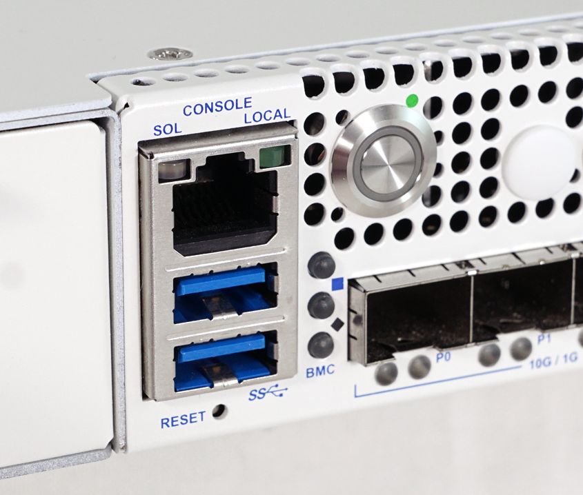
Close-up view of the Netgate 8300 Security Gateway Status LEDs
The Operating System status LEDs are labeled with shapes which correspond to each LED: Green Circle, Blue Square, and Black Diamond. The BMC status LED is labeled “BMC”.
OS Status LED Patterns
Description |
LED Pattern |
|---|---|
Standby |
Circle pulsing amber |
Power Applied |
Circle solid amber |
BIOS Booting |
Circle flashing green |
Running |
Circle solid green |
BMC Status LED Patterns
Description |
LED Pattern |
|---|---|
BMC Power Applied |
BMC solid amber |
BMC OS Booting |
BMC flashing blue |
BMC Boot Completed/Ready |
BMC solid blue |
Power Supply Unit LED Patterns
Each power supply has a status LED in the upper right corner (not pictured).
Description |
LED Pattern |
|---|---|
Power Applied + Power On |
PSU solid green |
Power Applied + Power Off |
PSU flashing green |
Power Loss to all PSUs |
PSU off |
Power Loss to one PSU [1] |
PSU flashing amber |
Warning Event [2] |
PSU flashing alternating amber and green |
Critical Event [3] |
PSU solid amber |
PSU LED Notes
Rear Panel
The rear panel of the device has items which are not meant to be accessed as often as the front, as the device is intended to be mounted in a rack.
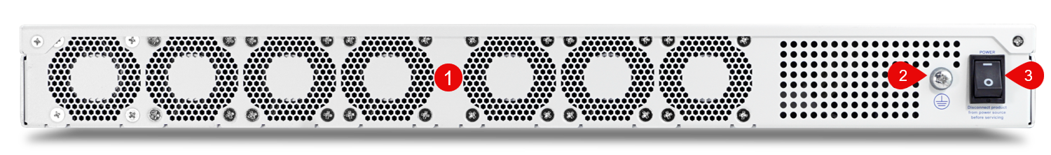
Rear side view of the Netgate 8300 Security Gateway with key items numbered
The items below are marked with numbers on figure Rear side view of the Netgate 8300 Security Gateway with key items numbered:
Item |
Description |
|---|---|
1 |
Fan exhaust grills |
2 |
Ground connection |
3 |
Power switch |