Add-On Expansion Card Installation
The Netgate® 8300 has two expansion card slots available for additional devices such as 25 Gbit/s or 100 Gbit/s network interface cards.
The two expansion card slots have the following capabilities:
1x PCIe 3.0 x8 LP (Low Profile) slot compatible with half-length low profile cards.
1x PCIe 4.0 x16 slot compatible with full-height three-quarter length cards.
See also
See Input and Output Ports for additional information on the expansion card slots.
Warnings and Precautions
Danger
Anti-static protection must be used throughout this procedure.
Danger
Take all appropriate precautions and exercise care when handling the exposed system board and add-on cards. There are many delicate components which can be damaged during this process. Damage caused via physical contact and electrostatic discharge while performing this installation is not covered by the warranty.
Warning
This device includes an intrusion detection sensor which operates even when the device is without power.
Opening the case on this device triggers an intrusion alarm which is logged by the BMC and is visible in the IPMI sensors. This alarm must be reset manually as described in Re-arm the Chassis Intrusion Switch.
When the intrusion alarm is active the fans run at a fixed speed of around 8500 RPM. Resetting the intrusion sensor alarm returns the fans to their profiled speed.
Required Tools and Hardware
Installing add-on expansion cards in the Netgate 8300 requires the following tools and hardware:
Phillips screwdriver
Anti-static grounding strap and anti-static mat for handling bare components and the 8300 system
Compatible expansion card
Installation Procedure
The installation procedure has many steps which are broken down into related groups in the remainder of this document. Follow all steps in the procedure carefully.
Take a Backup
If the system contains an existing configuration, then the first step is to take a backup of that configuration for safety.
If the existing configuration is not necessary, this section may be skipped.
There are numerous backup options covered in the TNSR software documentation section on Backup and Restore.
Power Off and Disconnect
For safety, before opening the case, the Netgate 8300 must be completely disconnected. This includes power, network cables, USB cables, serial console cables, and any other external cables or devices connected to the Netgate 8300.
Danger
Reminder:
Anti-static protection must be used throughout this procedure.
Any hardware damage incurred during this procedure is not covered by the hardware warranty.
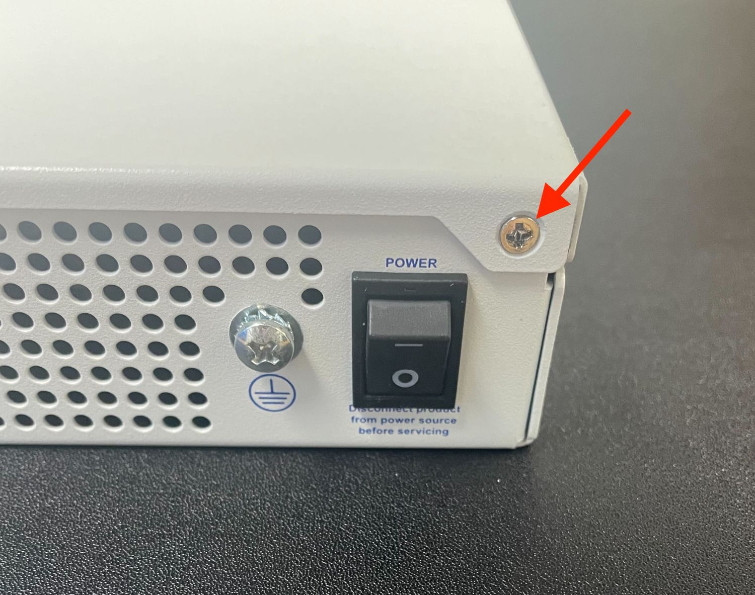
Turn power off to the unit by changing the power switch on the rear of the unit to the off position.
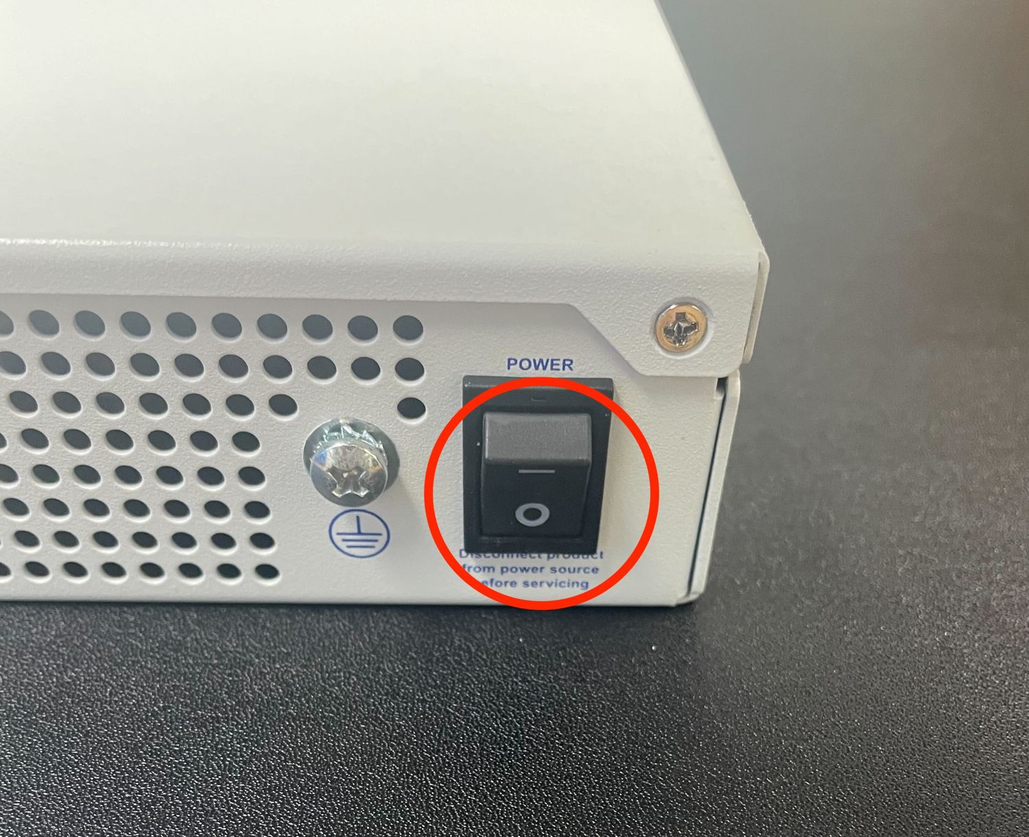
Power switch (circled) in the off position
Unplug the power cables from all installed power supply units (PSUs).
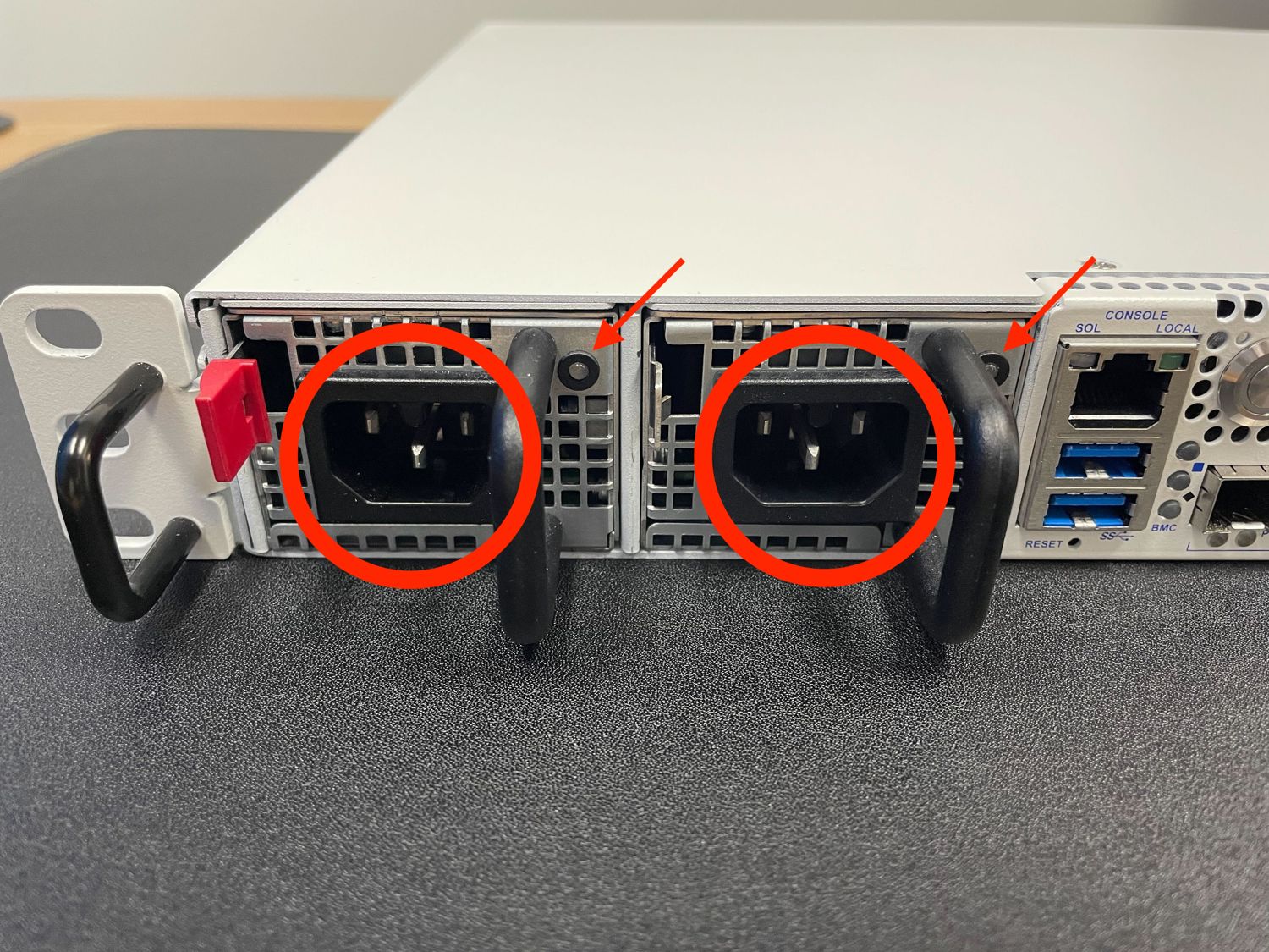
Power Supply Units with power receptacles circled, and status LEDs indicated with arrows
Danger
Wait at least 60 seconds after unplugging power to proceed. This ensures that all phantom power has dissipated.
The LED indicator on all installed PSUs should be off before proceeding.
Unplug all network cables, USB cables and devices, serial console connections, etc.
Dismount the Netgate 8300 from the rack
Move the Netgate 8300 to a safe work location such as an anti-static mat
Removing the Lid
The next portion of the procedure involves opening the device and removing the lid.
Danger
Reminder:
Anti-static protection must be used throughout this procedure.
Any hardware damage incurred during this procedure is not covered by the hardware warranty.
Remove the screws from the top of the case near the front of the unit using the Phillips head screwdriver.
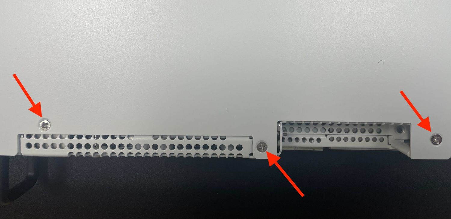
Screws on the top of the cover at the front of the unit, indicated with arrows
Remove the screw from the rear side of the unit in the top left corner using the Phillips head screwdriver.
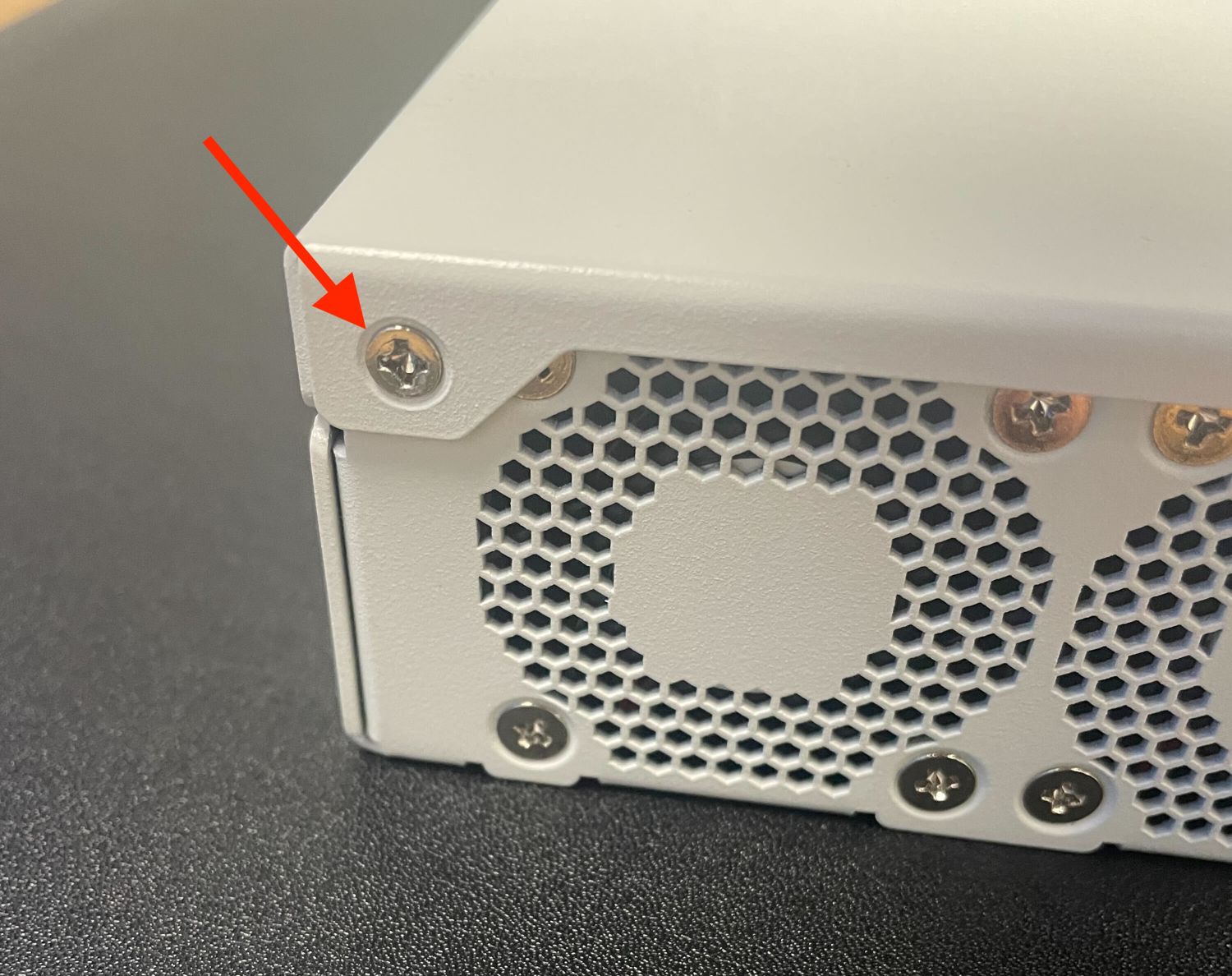
Screw on the rear side of the unit at the left top corner, indicated with an arrow.
Remove the screw from the rear side of the unit in the top right corner using the Phillips head screwdriver.
Screw on the rear side of the unit at the right top corner, indicated with an arrow.
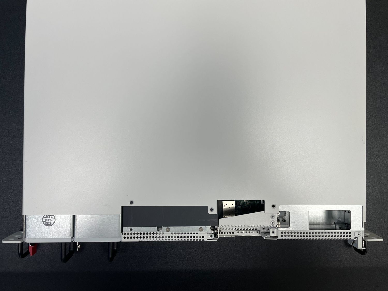
Slide the top cover back away from the front panel until it stops.
Sliding back the top cover away from the front panel
Lift off the top cover and set it aside, keeping it upright to avoid damaging the top surface.
Top cover in position to be lifted off
Remove the Expansion Riser Assembly
The add-on expansion card slots are located on a riser assembly. This riser assembly must be removed from the device to safely add or remove expansion cards.
Danger
Reminder:
Anti-static protection must be used throughout this procedure.
Any hardware damage incurred during this procedure is not covered by the hardware warranty.
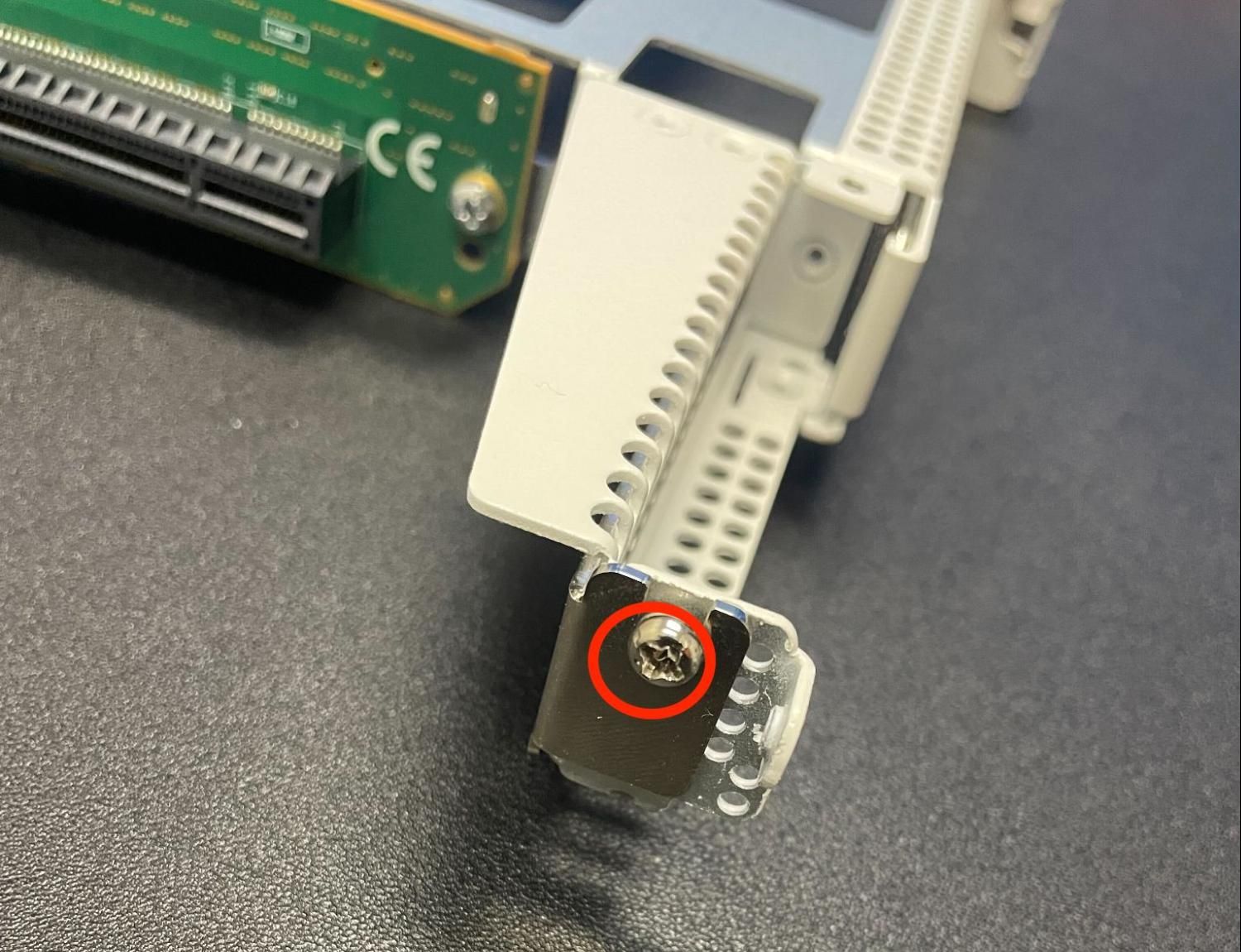
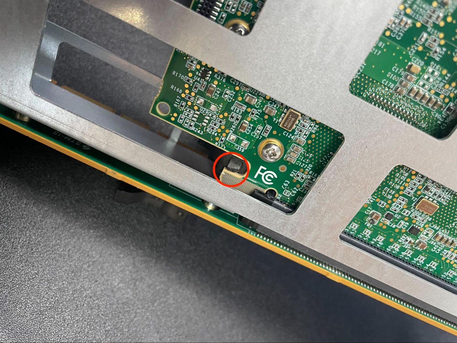
Loosen the two captive screws which attach the riser assembly to the motherboard using the Phillips head screwdriver.
Note
These screws are captive and will not fully remove from the riser assembly. It is sufficient to loosen the screws until they no longer attach the riser assembly to the motherboard. This may be felt as a soft “click” when the screw is freely rotating and the threads are not engaged.
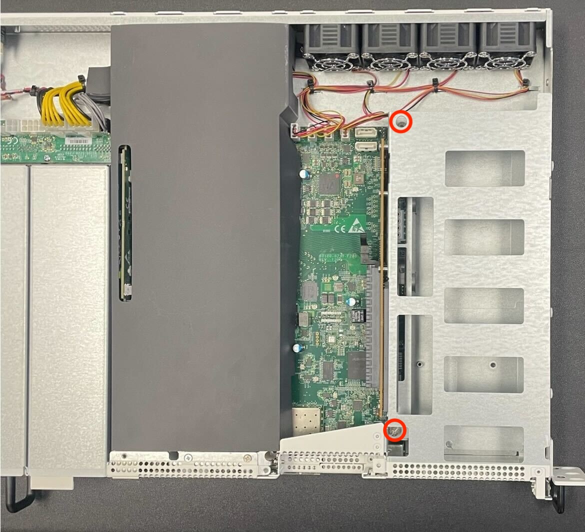
Location of the captive riser assembly retaining screws indicated with red circles
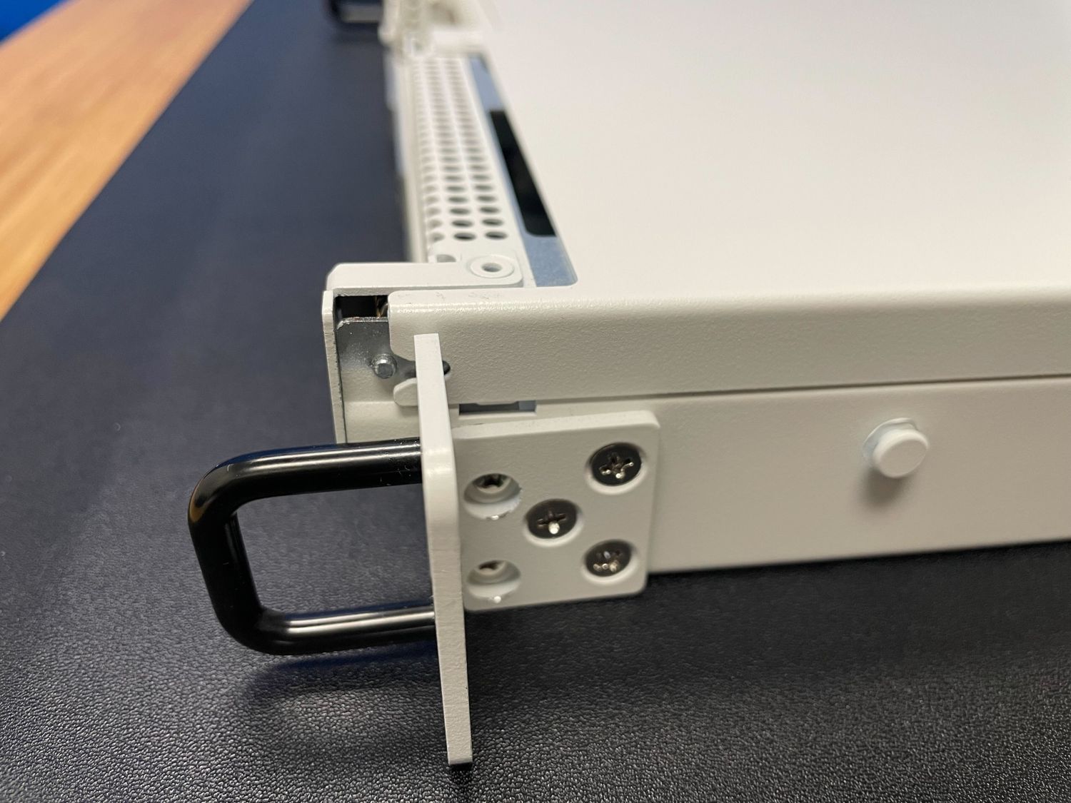
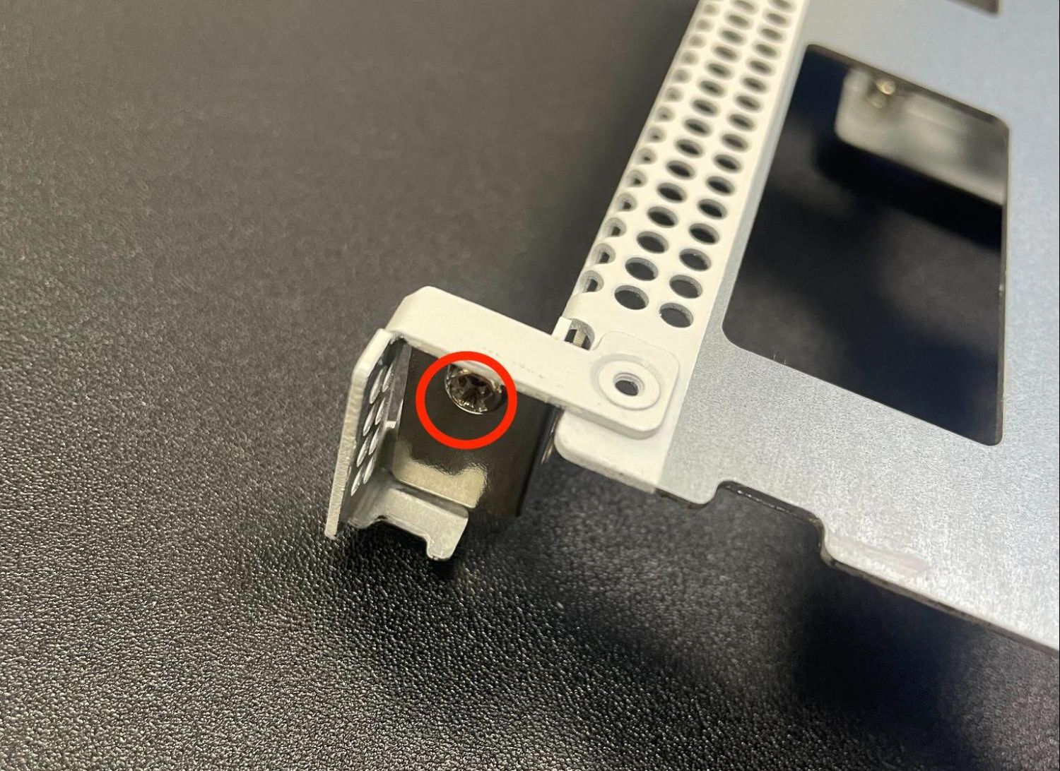
Remove the riser assembly retaining screw on the front of the unit using the Phillips head screwdriver.
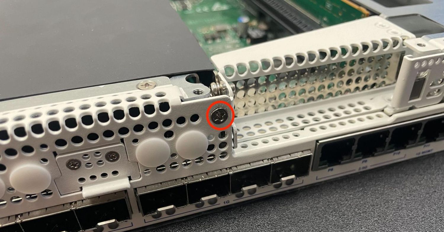
Location of the riser assembly retaining screw on the front of the unit indicated with a red circle
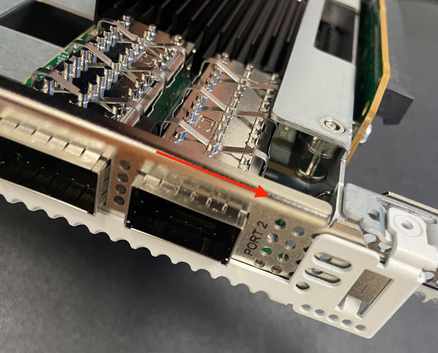
Carefully lift the riser assembly from the motherboard slot and remove the riser assembly.
Rotating the assembly as seen in figures below can help the removal process with PCIe cards installed.
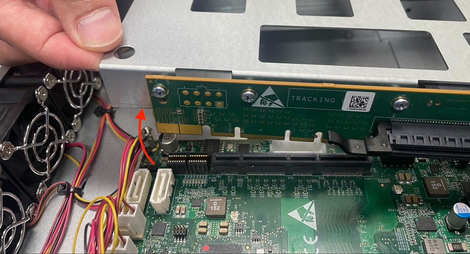
Lift the riser assembly from the rear to remove it from the riser slot on the motherboard
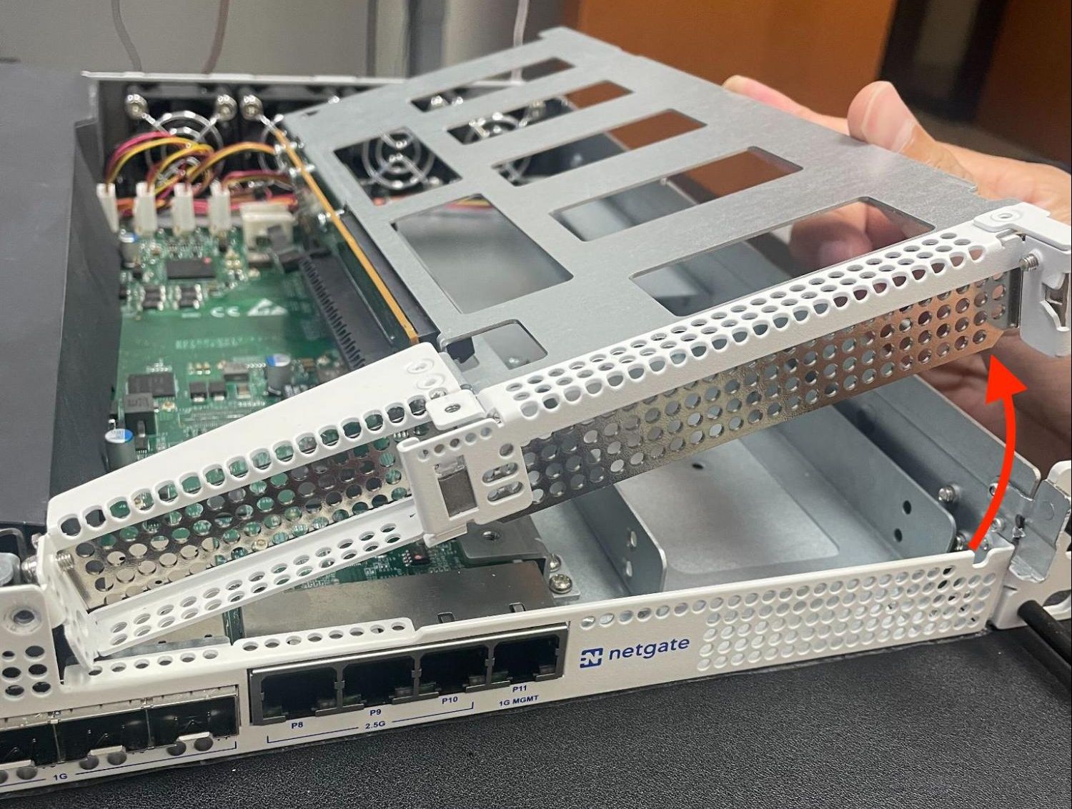
Lift and rotate the riser assembly from the front as indicated by the red arrow to remove it from the chassis
Install the Add-on Expansion Card
With the riser assembly removed, it is time to install the add-on expansion card.
Danger
Reminder:
Anti-static protection must be used throughout this procedure.
Any hardware damage incurred during this procedure is not covered by the hardware warranty.
Locate the appropriate slot for the expansion card
The expansion slot will vary depending on the card. For example, a card with a low profile bracket would most likely go in the smaller slot on the left, assuming its specifications match the slot capabilities. Some cards have alternate brackets so in those cases it is best to match the card based on its bus requirements, speed, and so on. See Input and Output Ports for the expansion slot specifications.
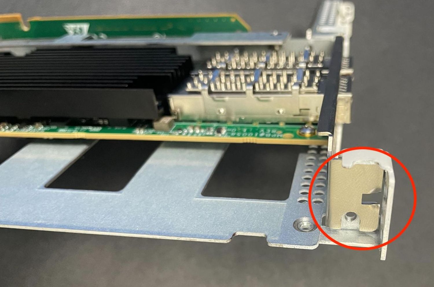
Loosen or remove the retaining screw from the expansion slot
Tip
It is not typically necessary to fully remove the screw as the card can be moved around it when it is loosened, but removing the screw can make installing or removing the cards easier.
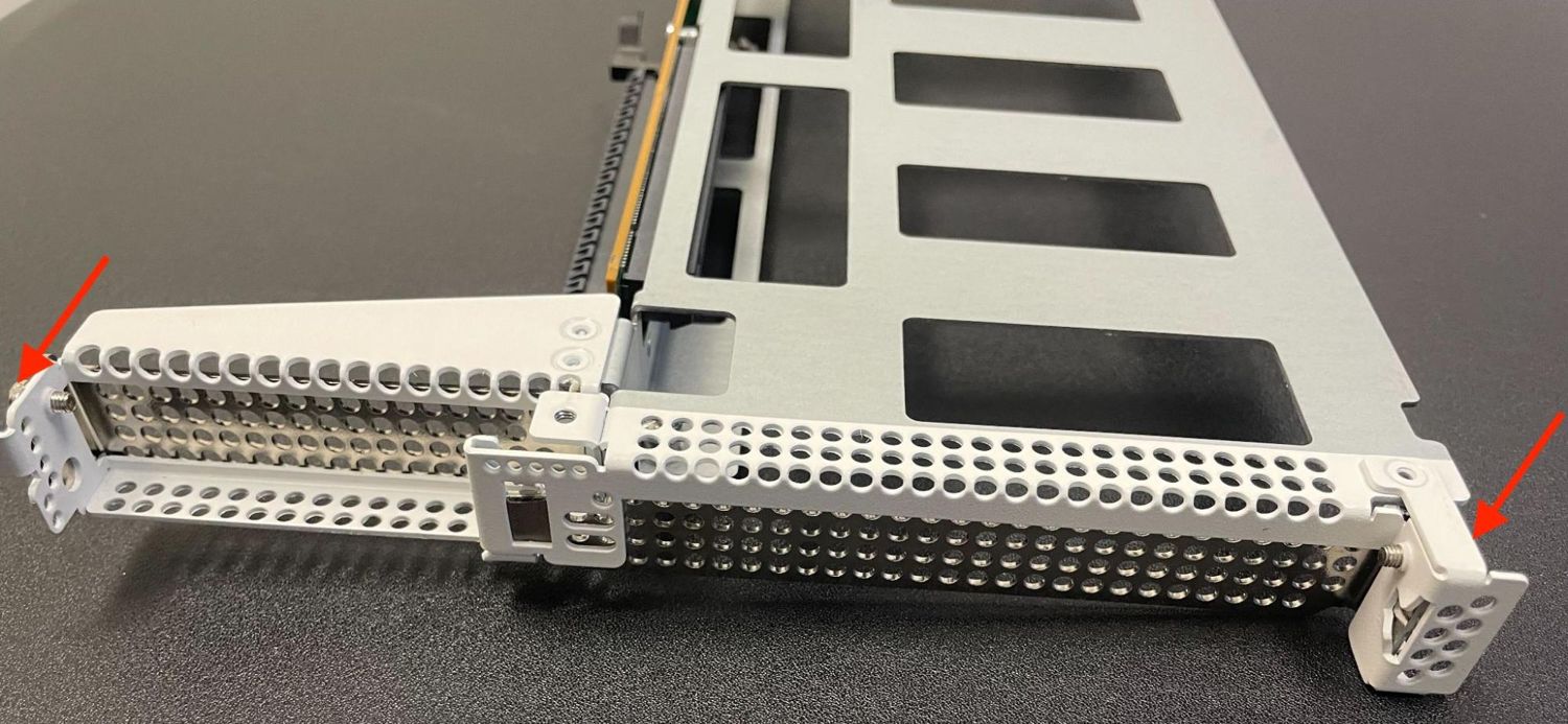
Location of the add-on expansion card slot retaining screws indicated with red arrows
Location of the low profile add-on expansion card slot retaining screw indicated with a red circle
Location of the full height add-on expansion card slot retaining screw indicated with a red circle
Remove the expansion slot cover by sliding it away from the center of the riser assembly and lifting it out, then set it aside.
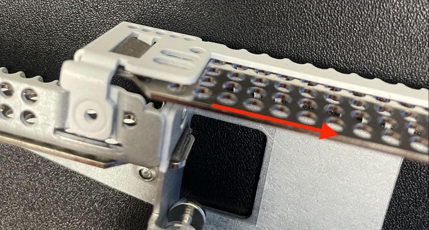
Slide the expansion slot cover away from the center of the riser assembly
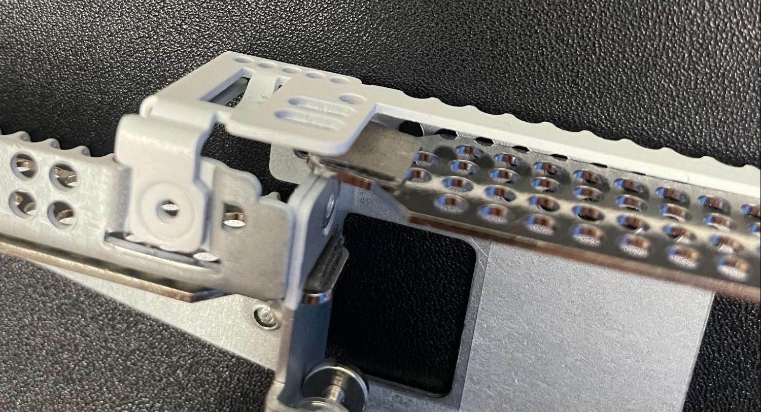
Remove the expansion slot cover once it is free from the expansion slot
Note
The cover will not be necessary so long as there is a card in the expansion slot. Store the cover in a safe place in case it is needed in the future.
Install the add-on card into the expansion card slot by sliding it toward the center of the riser assembly until it is fully seated in its socket.
Installing an add-on network interface card into an expansion slot
Ensure the card is properly aligned and fully inserted into the expansion card slot.
The rear of the socket has a retention clip to hold the card in place which should be engaged once the card is fully seated
Expansion card slot retention clip holding a card in place
The front of the card should be flush with the front of the riser assembly and aligned with the retention screw hole.
Expansion card aligned with the riser assembly and retention screw hole
Fasten the expansion card to the riser assembly using the retaining screw and the Phillips head screwdriver.
Expansion card fastened in the riser assembly using the retention screw
Replace the Riser Assembly
With the expansion card installed in the riser assembly, replace the riser assembly back into the chassis.
Danger
Reminder:
Anti-static protection must be used throughout this procedure.
Any hardware damage incurred during this procedure is not covered by the hardware warranty.
Insert the riser card back into the chassis and fully seat it into the slot on the motherboard.
Rotate and replace the riser assembly from the front in the opposite direction indicated by the red arrow
Re-seat the riser assembly in the riser slot from the rear of the motherboard in the opposite of the direction indicated by the red arrow
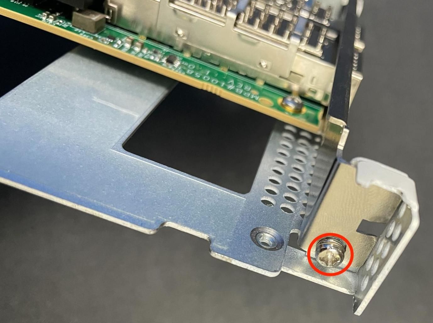
Replace the riser assembly retaining screw on the front of the unit using the Phillips head screwdriver.
Location of the riser assembly retaining screw on the front of the unit indicated with a red circle
Tighten the two captive screws which attach the riser assembly to the motherboard using the Phillips head screwdriver.
Location of the captive riser assembly retaining screws indicated with red circles
Replacing and Fastening the Lid
With the internal components all in place, the next step is to replace the lid and all its fasteners.
Danger
Reminder:
Anti-static protection must be used throughout this procedure.
Any hardware damage incurred during this procedure is not covered by the hardware warranty.
Align the top cover with the top of the unit, a short distance behind the front panel.
Top cover in position to be replaced
Slide the top cover toward the front of the unit into its closed position.
Slide the top cover back toward the front panel
Replace the screws on the rear of the unit (left and right top corners) using the Phillips head screwdriver.
Screw on the rear side of the unit at the left top corner, indicated with an arrow.
Screw on the rear side of the unit at the right top corner, indicated with an arrow.
Replace the screws on the top of the unit using the Phillips head screwdriver.
Screws on the top of the cover at the front of the unit, indicated with arrows
Reconnect
The device is now ready to be put back into its former location.
Mount the Netgate 8300 in the rack
Plug in all network cables, USB cables and devices, serial console connections, etc.
Insert the USB memstick containing the installation media
Plug the power cables into all installed power supply units.
Power Supply Units with power receptacles circled, and status LEDs indicated with arrows
Turn power on to the unit by changing the power switch on the rear of the unit to the on position.
Reconnect to the serial console
Enable Interfaces (Network Interface Cards Only)
If the expansion card added to the device is a network interface card, this must be accounted for in TNSR software once the card is in place.
The interfaces can be enabled for use in the dataplane as needed based on the information in the TNSR software documentation for dataplane interfaces.
See also
See Networking Ports for more information.
See also
Netgate TAC may be able to assist with adjusting configurations for customers in many cases.
Re-arm the Intrusion Sensor
Opening the case to install the expansion card will trigger the intrusion alarm sensor, even while the device is removed from power. The intrusion alarm causes the fans to run at a higher fixed speed until the sensor is re-armed.
Once TNSR software is up and running, follow the procedure in Re-arm the Chassis Intrusion Switch to reset the sensor.