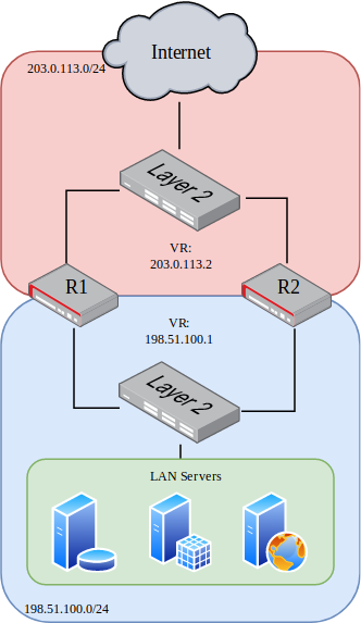
This example is a basic two-node VRRP cluster with one node as the owner
of an internal and external VR address, and the other as a backup. This
is a routed configuration with a statically routed subnet used for the internal
LAN.
In this example, the upstream ISP will deliver a routed subnet
(198.51.100.0/24) to the WAN-side VR address (203.0.113.2), and internal
clients will use the LAN-side VR address (198.51.100.1) as their gateway.
Interface tracking is included in the example to protect against a single
failure of either WAN or LAN.
See also
See VRRP Configuration for more information on how the commands in
the example function.
This information is for the secondary node, which in this example is called R2.
Note that the interface addresses are different than R1, but the same VR address
is used.
The configuration commands in this section show how the settings from the table
above are applied to each node. Some additional VRRP settings are shown in the
commands but not the tables, but they are using the default values, shown for
emphasis.
First, set the R1 interface names:
r1 tnsr(config)# dataplane dpdk dev 0000:06:00.0 network name WANr1 tnsr(config)# dataplane dpdk dev 0000:06:00.1 network name LANr1 tnsr(config)# service dataplane restart
Next, configure the R1 WAN interface:
r1 tnsr(config)# int WANr1 tnsr(config-interface)# ip address 203.0.113.2/24r1 tnsr(config-interface)# ip vrrp-virtual-router 220r1 tnsr(config-vrrp4)# preempt truer1 tnsr(config-vrrp4)# v3-advertisement-interval 100r1 tnsr(config-vrrp4)# priority 255r1 tnsr(config-vrrp4)# track-interface LAN priority-decrement 240r1 tnsr(config-vrrp4)# virtual-address 203.0.113.2r1 tnsr(config-vrrp4)# exitr1 tnsr(config-interface)# exitr1 tnsr(config)#
Next, configure the R1 LAN interface:
r1 tnsr(config)# int LANr1 tnsr(config-interface)# ip address 198.51.100.1/24r1 tnsr(config-interface)# ip vrrp-virtual-router 210r1 tnsr(config-vrrp4)# preempt truer1 tnsr(config-vrrp4)# v3-advertisement-interval 100r1 tnsr(config-vrrp4)# priority 255r1 tnsr(config-vrrp4)# track-interface WAN priority-decrement 240r1 tnsr(config-vrrp4)# virtual-address 198.51.100.1r1 tnsr(config-vrrp4)# exitr1 tnsr(config-interface)# exitr1 tnsr(config)#
R1 is now complete.
Set the R2 interface names:
r2 tnsr(config)# dataplane dpdk dev 0000:06:00.0 network name WANr2 tnsr(config)# dataplane dpdk dev 0000:06:00.1 network name LANr2 tnsr(config)# service dataplane restart
Configure the R2 WAN interface:
r2 tnsr(config)# int WANr2 tnsr(config-interface)# ip address 203.0.113.3/24r2 tnsr(config-interface)# ip vrrp-virtual-router 220r2 tnsr(config-vrrp4)# preempt truer2 tnsr(config-vrrp4)# accept-mode truer2 tnsr(config-vrrp4)# v3-advertisement-interval 100r2 tnsr(config-vrrp4)# priority 100r2 tnsr(config-vrrp4)# track-interface LAN priority-decrement 90r2 tnsr(config-vrrp4)# virtual-address 203.0.113.2r2 tnsr(config-vrrp4)# exitr2 tnsr(config-interface)# exitr2 tnsr(config)#
Finally, configure the R2 LAN interface:
r2 tnsr(config)# int LANr2 tnsr(config-interface)# ip address 198.51.100.2/24r2 tnsr(config-interface)# ip vrrp-virtual-router 210r2 tnsr(config-vrrp4)# preempt truer2 tnsr(config-vrrp4)# accept-mode truer2 tnsr(config-vrrp4)# v3-advertisement-interval 100r2 tnsr(config-vrrp4)# priority 100r2 tnsr(config-vrrp4)# track-interface WAN priority-decrement 90r2 tnsr(config-vrrp4)# virtual-address 198.51.100.1r2 tnsr(config-vrrp4)# exitr2 tnsr(config-interface)# exitr2 tnsr(config)#
At this point, the interface and VRRP configuration is complete for both nodes.
LAN clients in 198.51.100.0/24 can use the LAN VR address of
198.51.100.1 as their default gateway.
As mentioned in VRRP Compatibility, the example above cannot be used in
combination with NAT because r1 has a priority of 255 on its VR addresses.
To use VRRP with NAT, an additional address not used by either node is required
by TNSR for use as the VRRP virtual address.
The configuration is largely the same as above, with a few key differences. An
example for this configuration is covered in VRRP with Outside NAT.