Tip
This is the documentation for the 19.12 version. Looking for the documentation of the latest version? Have a look here.
Inter-VLAN Routing
Use Case
Inter-VLAN routing is a process of forwarding network traffic from one VLAN to another VLAN using a router or layer 3 device.
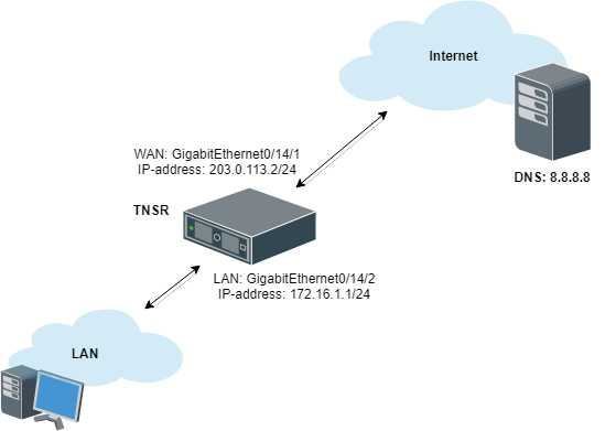
Example Scenario
This example configures TNSR with VLANs:
Item |
Value |
|---|---|
TNSR Internet Interface |
GigabitEthernet0/14/1 |
TNSR Internet Address |
203.0.113.2/24 |
TNSR Local Interface |
GigabitEthernet0/14/2 |
TNSR VLAN 10 Interface |
GigabitEthernet0/14/2.10 |
TNSR VLAN 10 Address |
172.16.10.1/24 |
TNSR VLAN 20 Interface |
GigabitEthernet0/14/2.20 |
TNSR VLAN 20 Address |
172.16.20.1/24 |
Inter-VLAN Routing Example
TNSR Configuration
A few pieces of information are necessary to create a VLAN subinterface (“subif”):
The parent interface which will carry the tagged traffic, e.g.
GigabitEthernet3/0/0The subinterface ID number, which is a positive integer that uniquely identifies this subif on the parent interface. It is commonly set to the same value as the VLAN tag
The VLAN tag used by the subif to tag outgoing traffic, and to use for identifying incoming traffic bound for this subif. This is an integer in the range
1-4095, inclusive. This VLAN must also be tagged on the corresponding switch configuration for the port used by the parent interface.
Create Subinterfaces
First, create subinterfaces for VLAN 10 and VLAN 20:
tnsr(config)# interface subif GigabitEthernet0/14/2 10
tnsr(config-subif)# dot1q 10
tnsr(config-subif)# exact-match
tnsr(config-subif)# exit
tnsr(config)# interface subif GigabitEthernet0/14/2 20
tnsr(config-subif)# dot1q 20
tnsr(config-subif)# exact-match
tnsr(config-subif)# exit
The subif interface appears with the parent interface name and the subif id,
joined by a ..
Configure Interfaces
At this point,subinterface behaves identically to a regular interface in that it may have an IP address, routing, and so on:
tnsr(config)# interface GigabitEthernet0/14/2.10
tnsr(config-interface)# ip address 172.16.10.1/24
tnsr(config-interface)# description VLAN10
tnsr(config-interface)# enable
tnsr(config-interface)# exit
tnsr(config)# interface GigabitEthernet0/14/2.20
tnsr(config-interface)# ip address 172.16.20.1/24
tnsr(config-interface)# description VLAN20
tnsr(config-interface)# enable
tnsr(config-interface)# exit
Configure DHCP
Next, configure the DHCP server and DHCP pool on TNSR for each VLAN.
For VLAN 10:
tnsr(config)# dhcp4 server
tnsr(config-kea-dhcp4)# description LAN DHCP Server
tnsr(config-kea-dhcp4)# interface listen GigabitEthernet0/14/2.10
tnsr(config-kea-dhcp4)# option domain-name
tnsr(config-kea-dhcp4-opt)# data example.com
tnsr(config-kea-dhcp4-opt)# exit
tnsr(config-kea-dhcp4)# subnet 172.16.10.0/24
tnsr(config-kea-subnet4)# pool 172.16.10.100-172.16.10.245
tnsr(config-kea-subnet4-pool)# exit
tnsr(config-kea-subnet4)# interface GigabitEthernet0/14/2.10
tnsr(config-kea-subnet4)# option domain-name-servers
tnsr(config-kea-subnet4-opt)# data 172.16.10.1
tnsr(config-kea-subnet4-opt)# exit
tnsr(config-kea-subnet4)# option routers
tnsr(config-kea-subnet4-opt)# data 172.16.10.1
tnsr(config-kea-subnet4-opt)# exit
tnsr(config-kea-dhcp4)# exit
And for VLAN 20:
tnsr(config)# dhcp4 server
tnsr(config-kea-dhcp4)# interface listen GigabitEthernet0/14/2.20
tnsr(config-kea-dhcp4)# subnet 172.16.20.0/24
tnsr(config-kea-subnet4)# pool 172.16.20.100-172.16.20.245
tnsr(config-kea-subnet4-pool)# exit
tnsr(config-kea-subnet4)# interface GigabitEthernet0/14/2.20
tnsr(config-kea-subnet4)# option domain-name-servers
tnsr(config-kea-subnet4-opt)# data 172.16.20.1
tnsr(config-kea-subnet4-opt)# exit
tnsr(config-kea-subnet4)# option routers
tnsr(config-kea-subnet4-opt)# data 172.16.20.1
tnsr(config-kea-subnet4-opt)# exit
tnsr(config-kea-dhcp4)# exit
tnsr(config)# dhcp4 enable
Configure Outbound NAT
Now configure Outbound NAT:
tnsr(config)# nat pool addresses 203.0.113.2
tnsr(config)# interface GigabitEthernet0/14/1
tnsr(config-interface)# ip nat outside
tnsr(config-interface)# exit
tnsr(config)# interface GigabitEthernet0/14/2.10
tnsr(config-interface)# ip nat inside
tnsr(config-interface)# exit
tnsr(config)# interface GigabitEthernet0/14/2.20
tnsr(config-interface)# ip nat inside
tnsr(config-interface)# exit
tnsr(config)# nat global-options nat44 forwarding true
tnsr(config)#
Configure DNS Resolver
Finally, configure a DNS Resolver in forwarding mode:
tnsr# configure
tnsr(config)# unbound server
tnsr(config-unbound)# interface 127.0.0.1
tnsr(config-unbound)# interface 172.16.10.1
tnsr(config-unbound)# interface 172.16.20.1
tnsr(config-unbound)# outgoing-interface 203.0.113.2
tnsr(config-unbound)# access-control 172.16.10.0/24 allow
tnsr(config-unbound)# access-control 172.16.20.0/24 allow
tnsr(config-unbound)# forward-zone .
tnsr(config-unbound-fwd-zone)# nameserver address 8.8.8.8
tnsr(config-unbound-fwd-zone)# nameserver address 8.8.4.4
tnsr(config-unbound-fwd-zone)# exit
tnsr(config-unbound)# exit
tnsr(config)# unbound enable
Now there are two VLANs on the physical “LAN” port and interface
GigabitEthernet0/14/2 now works as trunk port between TNSR and downstream
L2/L3 switch.
This switch must be configured to match the expected VLAN tags and it must also have access ports configured for clients on each VLAN.