Tip
This is the documentation for the 23.06 version. Looking for the documentation of the latest version? Have a look here.
Step 1: Prepare for Deployment
Before the deployment can begin, it is important to gather all needed hardware, software, and parameters in advance.
Prerequisites
Internet connectivity with a compatible ISP.
ISP CPE in routed mode (no NAT), bridged mode, or half bridge mode (PPPoE), if supported by the ISP and CPE.
Note
If the CPE does not support routed or bridged modes, then enable CPE features such as 1:1 NAT or “DMZ” mode mapping the external address of the CPE to an internal address to be used by TNSR. IPsec passthrough mode in the CPE, if present, can also be helpful if the CPE must perform NAT.
Create a reference diagram that shows the logical topology.
Review the TNSR Zero-to-Ping documentation.
A fixed (static) IP address for the TNSR WAN interface.
Use NAT-T (traversal) support to configure a private IP the TNSR WAN interface.
Management (web login, admin access) of the ISP modem.
Notes
IPsec tunnels work best on a fixed public IP address, changes to IP addresses require updates to configurations.
Reference Diagram
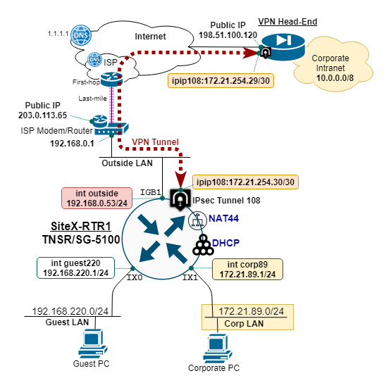
Create and maintain a reference diagram to support the deployment, as shown in the example below:

TNSR remote office reference diagram
Remote Office Deployment Parameters
Define and document the deployment parameters for the initial remote office setup, as shown in the example below:
Parameter |
Value |
|---|---|
TNSR Hostname |
siteX-rtr1 |
TNSR WAN Interface IP |
192.168.0.53/24 |
TNSR WAN Public IP |
203.0.113.65/24 |
Guest LAN Name |
GUEST220 |
Guest LAN IP |
192.168.220.1/24 |
Guest DHCP Range |
100-199 |
Guest DNS IP |
1.1.1.1,9.9.9.9 |
Corporate LAN Name |
CORP89 |
Corporate LAN IP |
172.21.89.1/24 |
Corporate DHCP Range |
100-199 |
Corporate DNS IP |
10.10.10.75,1.1.1.1 |
In this example, the Remote Office is deployed behind an ISP cable modem performing NAT. TNSR uses NAT-T to float the encrypted traffic up to UDP port 4500. This ensures the external NAT device (i.e. ISP site modem/router) does not block the IPsec traffic.
TNSR WAN IP is different than the ISP Modem Public IP address.
ISP cable modem provides NAT for inside devices, which includes the TNSR WAN interface.
IPsec VPN Tunnel Parameters
Define and document the parameters for the corporate IPsec tunnel and IP routing configuration, as shown in the example below:
Parameter |
Value |
|---|---|
TNSR WAN IP |
192.168.0.53/24 |
TNSR Public IP |
203.0.113.65/24 |
IPsec Tunnel Peer IP |
198.51.100.120 |
IPsec Tunnel ID |
108 |
IPsec IKEv2 Crypto |
AES128/SHA1/DH14 |
IPsec IKEv2 Authen |
PRE-SHARED-KEY |
IPsec Child SA Crypto |
AES128GCM16/DH14 |
IPsec Tunnel IP |
172.21.254.30/30 |
IPsec Tunnel Next-hop |
172.21.254.29 |
Corporate IP Block |
10.0.0.0/8 |