Tip
This is the documentation for the 19.12 version. Looking for the documentation of the latest version? Have a look here.
VRRP Example
This example is a basic two-node VRRP cluster with one node as the owner of an internal and external VR address, and the other as a backup. This is a routed configuration with a statically routed subnet used for the internal LAN.
In this example, the upstream ISP will deliver a routed subnet
(198.51.100.0/24) to the WAN-side VR address (203.0.113.2), and internal
clients will use the LAN-side VR address (198.51.100.1) as their gateway.
Diagram
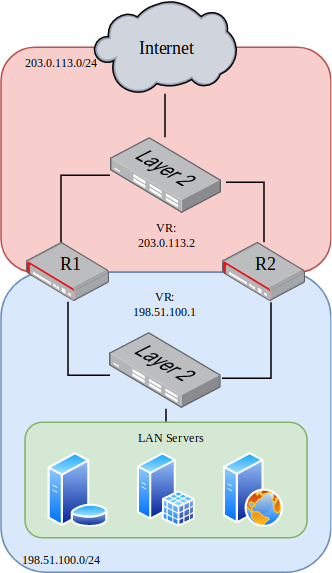
VRRP Example Diagram
Required Information
These tables contain all required information to configure the cluster.
The information in this first table is related to the setup in general, not a specific cluster node.
Item |
Value |
|---|---|
Upstream Gateway |
203.0.113.1 |
Routed Subnet |
198.51.100.0/24 |
LAN Client Gateway |
198.51.100.1 |
This information is for the primary node, which in this example is called R1.
Item |
Value |
|---|---|
R1 WAN Interface |
TenGigabitEthernet6/0/0 |
R1 WAN IP Address |
203.0.113.2/24 |
R1 WAN VR ID |
220 |
R1 WAN VR Address |
203.0.113.2 |
R1 WAN VR Priority |
255 (Owner) |
R1 LAN Interface |
TenGigabitEthernet6/0/1 |
R1 LAN IP Address |
198.51.100.1/24 |
R1 LAN VR ID |
210 |
R1 LAN VR Address |
198.51.100.1 |
R1 LAN VR Priority |
255 (Owner) |
This information is for the secondary node, which in this example is called R2. Note that the interface addresses are different than R1, but the same VR address is used.
Item |
Value |
|---|---|
R2 WAN Interface |
TenGigabitEthernet6/0/0 |
R2 WAN IP Address |
203.0.113.3/24 |
R2 WAN VR ID |
220 |
R2 WAN VR Address |
203.0.113.2 |
R2 WAN VR Priority |
100 |
R2 LAN Interface |
TenGigabitEthernet6/0/1 |
R2 LAN IP Address |
198.51.100.2/24 |
R2 LAN VR ID |
210 |
R2 LAN VR Address |
198.51.100.1 |
R2 LAN VR Priority |
100 |
Example Configuration
The configuration commands in this section show how the settings from the table above are applied to each node. Some additional VRRP settings are shown in the commands but not the tables, but they are using the default values, shown for emphasis.
First, configure the R1 WAN interface:
r1 tnsr(config)# int TenGigabitEthernet6/0/0
r1 tnsr(config-interface)# description WAN
r1 tnsr(config-interface)# ip address 203.0.113.2/24
r1 tnsr(config-interface)# ip vrrp-virtual-router 220
r1 tnsr(config-vrrp4)# preempt true
r1 tnsr(config-vrrp4)# priority 255
r1 tnsr(config-vrrp4)# v3-advertisement-interval 100
r1 tnsr(config-vrrp4)# virtual-address 203.0.113.2
r1 tnsr(config-vrrp4)# exit
r1 tnsr(config-interface)# exit
r1 tnsr(config)#
Next, configure the R1 LAN interface:
r1 tnsr(config)# int TenGigabitEthernet6/0/1
r1 tnsr(config-interface)# description LAN
r1 tnsr(config-interface)# ip address 198.51.100.1/24
r1 tnsr(config-interface)# ip vrrp-virtual-router 210
r1 tnsr(config-vrrp4)# preempt true
r1 tnsr(config-vrrp4)# priority 255
r1 tnsr(config-vrrp4)# v3-advertisement-interval 100
r1 tnsr(config-vrrp4)# virtual-address 198.51.100.1
r1 tnsr(config-vrrp4)# exit
r1 tnsr(config-interface)# exit
r1 tnsr(config)#
R1 is now complete. Move on to the R2 WAN interface:
r2 tnsr(config)# int TenGigabitEthernet6/0/0
r2 tnsr(config-interface)# description WAN
r2 tnsr(config-interface)# ip address 203.0.113.3/24
r2 tnsr(config-interface)# ip vrrp-virtual-router 220
r2 tnsr(config-vrrp4)# preempt true
r2 tnsr(config-vrrp4)# priority 100
r2 tnsr(config-vrrp4)# v3-advertisement-interval 100
r2 tnsr(config-vrrp4)# virtual-address 203.0.113.2
r2 tnsr(config-vrrp4)# exit
r2 tnsr(config-interface)# exit
r2 tnsr(config)#
Finally, configure the R2 LAN interface:
r2 tnsr(config)# int TenGigabitEthernet6/0/1
r2 tnsr(config-interface)# description LAN
r2 tnsr(config-interface)# ip address 198.51.100.2/24
r2 tnsr(config-interface)# ip vrrp-virtual-router 210
r2 tnsr(config-vrrp4)# preempt true
r2 tnsr(config-vrrp4)# priority 100
r2 tnsr(config-vrrp4)# v3-advertisement-interval 100
r2 tnsr(config-vrrp4)# virtual-address 198.51.100.1
r2 tnsr(config-vrrp4)# exit
r2 tnsr(config-interface)# exit
r2 tnsr(config)#
At this point, the interface and VRRP configuration is complete for both nodes.
LAN clients in 198.51.100.0/24 can use the LAN VR address of
198.51.100.1 as their default gateway.