High Availability Configuration Example
This recipe describes a simple three interface HA configuration. The three interfaces are LAN, WAN, and Sync. This is functionally equivalent to a two interface LAN and WAN deployment, with the Sync interface being used to synchronize configuration and firewall states between the primary and secondary firewalls.
Note
This example only covers an IPv4 configuration. High Availability is compatible with IPv6, but it requires static addressing on the firewall interfaces. When preparing to configure HA, if static IPv6 assignments are not available, set IPv6 to None on all interfaces.
See also
Review High Availability before following this recipe.
For help diagnosing issues with HA, see:
Determine IP Address Assignments
The first task is to plan IP address assignments. A good strategy is to use the lowest usable IP address in the subnet as the CARP VIP, the next subsequent IP address as the primary firewall interface IP address, and the next IP address as the secondary firewall interface IP address. This design is optional, any scheme may be used, but the best practice is to use a consistent and logical scheme to make design and administration simpler.
WAN Addressing
The WAN addresses will be selected from those assigned by the ISP. For the
example in Table WAN IP Address Assignments, the WAN of the HA
pair is 198.51.100.0/24, and the addresses 198.51.100.200 through
198.51.100.202 will be used as the WAN IP addresses.
IP Address |
Usage |
|---|---|
|
CARP shared IP address |
|
Primary node WAN IP address |
|
Secondary node WAN IP address |
LAN Addressing
The LAN subnet is 192.168.1.0/24. For this example, the LAN IP addresses will be assigned as shown in Table LAN IP Address Assignments.
IP Address |
Usage |
|---|---|
|
CARP shared IP address |
|
Primary node LAN IP address |
|
Secondary node LAN IP address |
Sync Interface Addressing
There is no shared CARP VIP on this interface because there is no need for one. These IP addresses are used only for communication between the firewalls. For this example, 172.16.1.0/24 is used as the Sync subnet. Only two IP addresses will be used, but a /24 is used to be consistent with the other internal interface (LAN). For the last octet of the IP addresses, use the same last octet as that firewall’s LAN IP address for consistency.
IP Address |
Usage |
|---|---|
|
Primary node Sync IP address |
|
Secondary node Sync IP address |
Figure Example HA Network Diagram shows the layout of this example HA pair. The primary and secondary each have identical connections to the WAN and LAN, and a crossover cable between them to connect the Sync interfaces. In this basic example, the WAN switch and LAN switch are still potential single points of failure. Switching redundancy is covered later in this chapter in Layer 2 Redundancy.
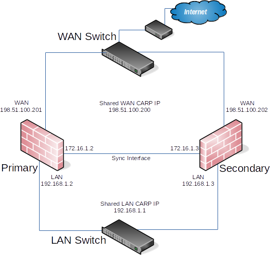
Example HA Network Diagram
Cluster Configuration Basics
Each node requires some basic configuration outside of the actual HA setup. Do not connect both nodes into the same LAN before both nodes have a non-conflicting LAN setup.
Installation, interface assignment and basic configuration
Install the OS on the firewalls as usual and assign the interfaces identically on both nodes.
Warning
Interfaces must be assigned in the same order on all nodes exactly. If the interfaces are not aligned, configuration synchronization and other tasks will not behave correctly. If any adjustments have been made to the interface assignments, they must be replicated identically on both nodes.
Then, connect to the GUI and use the Setup Wizard to configure each firewall with a unique hostname and non-conflicting static IP addresses. Refer back to Setup Wizard if needed.
For example, one node could be firewall-a.example.com and the other
firewall-b.example.com, or a more personalized pair of names.
Note
Avoid naming the nodes master or backup since those are states and
not roles, instead they could be named primary and secondary.
The default LAN IP address is 192.168.1.1. Each node must be moved to its
own address, such as 192.168.1.2 for the primary node and 192.168.1.3
for the secondary node. This layout is shown in
LAN IP Address Assignments. Once each node has a unique LAN IP
address, then both nodes may be plugged into the same LAN switch.
Setup Sync Interface
Before proceeding, the Sync interfaces on the cluster nodes must be configured. Sync IP Address Assignments lists the addresses to use for the Sync interfaces on each node. Once that has been completed on the primary node, perform it again on the secondary node with the appropriate IPv4 address value.
To complete the Sync interface configuration, add firewall rules on both nodes to allow synchronization.
At a minimum, the firewall rules must pass the configuration synchronization
traffic (by default, HTTPS on port 443) and pfsync traffic. In most cases, a
simple “allow all” style rule is used.
When complete, the rules will look like the example in figure Example Sync Interface Firewall Rules, which also includes a rule to allow ICMP echo (ping) for diagnostic purposes.
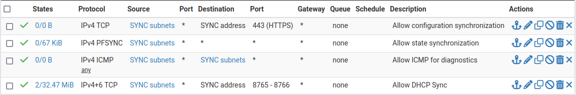
Example Sync Interface Firewall Rules
The secondary does not need those rules initially, only a rule to allow traffic to the GUI for XMLRPC to function. The full set of rules will synchronize once XMLRPC has been configured.
Configure State Synchronization (pfsync)
State synchronization using pfsync must be configured on both the primary and secondary nodes to function.
First on the primary node and then on the secondary, perform the following:
Navigate to System > High Avail Sync
Check Synchronize States
Set Synchronize Interface to SYNC
Set a custom Filter Host ID
For example,
1on the primary node,2on the secondary node.Set pfsync Synchronize Peer IP to the other node
Set this to
172.16.1.3on the primary node, or172.16.1.2on the secondary nodeClick Save
Configure Configuration Synchronization (XMLRPC)
Warning
Configuration synchronization must only be configured on the primary node. Never activate options in this section on the secondary node of a two-member cluster.
On the primary node only, perform the following:
Navigate to System > High Avail Sync
Set Synchronize Config to IP to the Sync interface IP address on the secondary node,
172.16.1.3Set Remote System Username to
admin.Note
This must be
admin, or the same user on both nodes with the “System - HA node sync” privilegeSet Remote System Password to the admin user account password, and repeat the value in the confirmation box.
Check the boxes for each area to synchronize to the secondary node. For this guide, as with most configurations, all boxes are checked. The Toggle All button may be used to select all of the options at once, rather than selecting them individually.
Click Save
As a quick confirmation that the synchronization worked, on the secondary node navigate to Firewall > Rules on the SYNC tab. The rules entered on the primary are now there, and the temporary rule is gone.
The two nodes are now linked for configuration synchronization! Changes made to the primary node in supported areas will be synchronized to the secondary whenever a change is made.
Warning
Do not make changes to the secondary in areas set to be synchronized! These changes will be overwritten the next time the primary node performs a synchronization.
Configuring the CARP Virtual IPs
With configuration synchronization in place, the CARP Virtual IP addresses need only be added to the primary node and they will be automatically copied to the secondary.
Navigate to Firewall > Virtual IPs on the primary node to manage CARP VIPs
Click
 Add at the top of the list to create a new VIP.
Note
Each interface handling user traffic must have a CARP VIP, in this case WAN and LAN.
Fill in the VIP options as described below. Refere to VIP Configuration Options for more information on the options in general.
- Type
Defines the type of VIP, in this case CARP.
- Interface
Defines the interface upon which the VIP will reside, such as WAN
- Address(es)
The Address box is where the IP address values are entered for the VIP. A subnet mask must also be selected and it must match the subnet mask on the interface IP address. For this example, enter
198.51.100.200and24(See WAN IP Address Assignments).- Virtual IP Password
Sets the password for the CARP VIP. This need only match between the two nodes, which will be handled by synchronization. The password and confirm password box must both be filled in and they must match.
- VHID Group
Defines the ID for the CARP VIP A common tactic is to make the VHID match the last octet of the IP address, so in this case choose
200- Advertising Frequency
Determines how often the node sends CARP heartbeats.
- Base
Controls how many whole seconds elapse between Heartbeats, typically 1.
This should match between cluster nodes.
- Skew
Controls fractions of a second (1/256th increments).
A primary node is typically set to 0 or 1, secondary nodes will be 100 or higher. This adjustment is handled automatically by XMLRPC synchronization.
- Description
Some text to identify the VIP, such as
WAN CARP VIP.
Note
If CARP appears to be too sensitive to latency on a given network, adjusting the Base by adding one second at a time is recommended until stability is achieved.
The above description used the WAN VIP as an example. The LAN VIP would be
configured similarly except it will be on the LAN interface and the address
will be 192.168.1.1 (See LAN IP Address Assignments).
If there are any additional IP addresses in the WAN subnet that will be used for purposes such as 1:1 NAT, port forwards, VPNs, etc, add them now.
Click Apply Changes after making any edits to the VIPs.
After adding VIPs, check Firewall > Virtual IPs on the secondary node to ensure that the VIPs synchronized as expected.
The Virtual IP addresses on both nodes will look like CARP Virtual IP Address List if the process was successful.
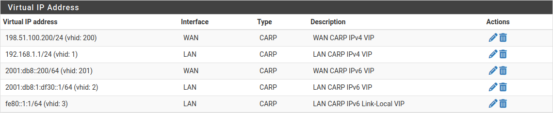
CARP Virtual IP Address List
Tip
For HA setups designed with multiple CARP VIPs on the same interface, instead consider adding the additional CARP VIPs as IP alias VIPs which use a single CARP VIP as their parent interface. This reduces the number of CARP VIP heartbeats on a network segment and also allows the VIPs to fail as a group. For details, see Using IP Aliases to Reduce Heartbeat Traffic.
Configure Outbound NAT for CARP
The next step will be to configure NAT so that the firewall will translate traffic from clients on the LAN to the shared WAN IP as the address as it exits.
Navigate to Firewall > NAT, Outbound tab
Click to select Hybrid Outbound NAT rule generation
Click Save
This mode allows the default NAT rules to stay in place, but be overridden by manually created rules for CARP. This way it becomes unnecessary to manage entries for the firewall itself (which should not use the CARP VIP for NAT) and also can make the process less disruptive when adding new interfaces later.
A set of rules will appear that are the equivalent rules to those in place for Automatic Outbound NAT. Adjust the rules for internal subnet sources to work with the CARP IP address instead.
Click
 below the Mappings section to add a new rule
Configure the rule as follows:
- Interface
WAN
- Address Family
IPv4
- Source
Network, then enter the LAN subnet, e.g.
192.168.1.0/24- Translation, Address
Choose the WAN CARP VIP from the Address drop-down, 198.51.100.200
- Description
LAN to WAN
Leave all other options at the default values.
Click Save
Click
below the Mappings section to add another new rule to
the top of the list for IPsec pass-through.Note
This is optional and may be omitted if there will not be any LAN clients which connect to external IPsec servers which lack NAT-T support.
Configure the rule as follows:
- Interface
WAN
- Address Family
IPv4
- Source
Network, then enter the LAN subnet, e.g.
192.168.1.0/24- Destination
- Type
Any
- Port
500
- Translation
- Address
Choose the WAN CARP VIP from the Address drop-down, 198.51.100.200
- Port or Range
Check Static Port
- Description
ISAKMP - LAN to WAN
Leave all other options at the default values.
Click Save
Click Apply Changes
Warning
If an additional local interface is added later, such as a second LAN, DMZ, etc, and that interface uses private IP addresses, then additional outbound NAT rules must be added at that time. Similarly, if additional WANs are added later, they will also need a set of outbound NAT rules.
Danger
Do not use an overly permissive source on outbound NAT rules! If an outbound NAT rule matches traffic from the firewall using a VIP, it can break several protocols and cause instability. Use only local/internal networks as the source on NAT rules, or an alias containing them.
Using Localhost as a source is also appropriate but the translation address for traffic from localhost should be an interface address and not a CARP VIP.
When complete, the rule changes will look like those found in Outbound NAT Rules for LAN with CARP VIP
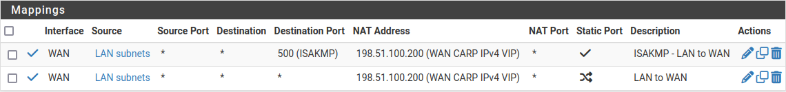
Outbound NAT Rules for LAN with CARP VIP
Modifying the DHCP Server
The DHCP server daemons on the cluster nodes need adjustments so that they can work together. The changes will synchronize from the primary to the secondary, so as with the VIPs and Outbound NAT, these changes need only be made on the primary node.
Navigate to Services > DHCP Server, LAN tab
Set the DNS Server to the LAN CARP VIP, here
192.168.1.1Set the Gateway to the LAN CARP VIP, here
192.168.1.1Set the Failover Peer IP to the actual LAN IP address of the secondary node, here
192.168.1.3Click Save
Setting the DNS Server and Gateway to a CARP VIP ensures that the local clients are talking to the failover address and not directly to either node. This way if the primary fails, the local clients will continue talking to the secondary node.
The Failover Peer IP allows the daemon to communicate with the peer directly in this subnet to exchange data such as lease information. When the settings synchronize to the secondary, this value is adjusted automatically so the secondary points back to the primary.
Finish Up & Test
At this point the cluster is configured and ready to use. Review the testing procedure in Verifying Failover Functionality to confirm it is operating properly.
Once everything tests OK, make configuration backups of both nodes.