Inter-VLAN Routing
Use Case
Inter-VLAN routing is a process of forwarding network traffic from one VLAN to another VLAN using a router or layer 3 device.
TNSR will automatically route traffic between directly connected networks provided that hosts on each network send their traffic to TNSR. Thus, this recipe focuses primarily on configuring TNSR to act as the default gateway for multiple VLANs as that is a typical deployment for this use case.
Example Scenario
This example configures TNSR with VLANs:
Item |
Value |
|---|---|
TNSR Internet Interface |
GigabitEthernet0/14/1 |
TNSR Internet Address |
203.0.113.2/24 |
TNSR Local Interface |
GigabitEthernet0/14/2 |
TNSR VLAN 10 Interface |
GigabitEthernet0/14/2.10 |
TNSR VLAN 10 Address |
172.16.10.1/24 |
TNSR VLAN 20 Interface |
GigabitEthernet0/14/2.20 |
TNSR VLAN 20 Address |
172.16.20.1/24 |
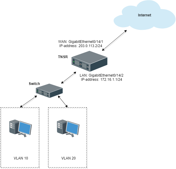
Inter-VLAN Routing Example
Hosts on VLAN 10 and VLAN 20 will use TNSR as their default gateway with addresses assigned by DHCP, and DNS handled by Unbound on TNSR. When attempting to reach the Internet through TNSR, hosts on VLAN 10 and VLAN 20 will have outbound NAT applied. Hosts in VLAN 10 can reach hosts in VLAN 20 automatically, and vice versa, provided that they each use TNSR as their default gateway.
Note
While this example recipe covers the default gateway scenario it is also possible to achieve this goal in other more advanced ways. For example, static routes or dynamic routing protocols can direct specific traffic to TNSR. Those are beyond the scope of this recipe.
Tip
ACLs can filter traffic between interfaces to limit exposure between the VLANs. Limiting traffic allowed between local networks is the best practice for security where possible.
TNSR Configuration
A few pieces of information are necessary to create VLAN Sub-interfaces, also known as “subif”s:
The parent interface which will carry the tagged traffic, e.g.
GigabitEthernet3/0/0The sub-interface ID number, which is a positive integer that uniquely identifies this subif on the parent interface. It is commonly set to the same value as the VLAN tag
The VLAN tag used by the subif to tag outgoing traffic, and to use for identifying incoming traffic bound for this subif. This is an integer in the range
1-4095, inclusive. This VLAN must also be tagged on the corresponding switch configuration for the port used by the parent interface.
Create Sub-interfaces
First, create sub-interfaces for VLAN 10 and VLAN 20:
tnsr(config)# interface subif GigabitEthernet0/14/2 10
tnsr(config-subif)# dot1q 10
tnsr(config-subif)# exact-match
tnsr(config-subif)# exit
tnsr(config)# interface subif GigabitEthernet0/14/2 20
tnsr(config-subif)# dot1q 20
tnsr(config-subif)# exact-match
tnsr(config-subif)# exit
The sub-interface appears with the parent interface name and the subif ID,
joined by a ..
Configure Interfaces
At this point, a sub-interface behaves identically to a regular interface in that it may have an IP address, routing, and so on:
tnsr(config)# interface GigabitEthernet0/14/2.10
tnsr(config-interface)# ip address 172.16.10.1/24
tnsr(config-interface)# description VLAN10
tnsr(config-interface)# enable
tnsr(config-interface)# exit
tnsr(config)# interface GigabitEthernet0/14/2.20
tnsr(config-interface)# ip address 172.16.20.1/24
tnsr(config-interface)# description VLAN20
tnsr(config-interface)# enable
tnsr(config-interface)# exit
Configure DHCP
Next, configure the DHCP server and DHCP pool on TNSR for each VLAN.
For VLAN 10:
tnsr(config)# dhcp4 server
tnsr(config-kea-dhcp4)# description LAN DHCP Server
tnsr(config-kea-dhcp4)# interface listen GigabitEthernet0/14/2.10
tnsr(config-kea-dhcp4)# lease lfc-interval 3600
tnsr(config-kea-dhcp4)# option domain-name
tnsr(config-kea-dhcp4-opt)# data example.com
tnsr(config-kea-dhcp4-opt)# exit
tnsr(config-kea-dhcp4)# subnet 172.16.10.0/24
tnsr(config-kea-subnet4)# id 10
tnsr(config-kea-subnet4)# pool 172.16.10.100-172.16.10.245
tnsr(config-kea-subnet4-pool)# exit
tnsr(config-kea-subnet4)# interface GigabitEthernet0/14/2.10
tnsr(config-kea-subnet4)# option domain-name-servers
tnsr(config-kea-subnet4-opt)# data 172.16.10.1
tnsr(config-kea-subnet4-opt)# exit
tnsr(config-kea-subnet4)# option routers
tnsr(config-kea-subnet4-opt)# data 172.16.10.1
tnsr(config-kea-subnet4-opt)# exit
tnsr(config-kea-dhcp4)# exit
And for VLAN 20:
tnsr(config)# dhcp4 server
tnsr(config-kea-dhcp4)# interface listen GigabitEthernet0/14/2.20
tnsr(config-kea-dhcp4)# lease lfc-interval 3600
tnsr(config-kea-dhcp4)# subnet 172.16.20.0/24
tnsr(config-kea-subnet4)# id 20
tnsr(config-kea-subnet4)# pool 172.16.20.100-172.16.20.245
tnsr(config-kea-subnet4-pool)# exit
tnsr(config-kea-subnet4)# interface GigabitEthernet0/14/2.20
tnsr(config-kea-subnet4)# option domain-name-servers
tnsr(config-kea-subnet4-opt)# data 172.16.20.1
tnsr(config-kea-subnet4-opt)# exit
tnsr(config-kea-subnet4)# option routers
tnsr(config-kea-subnet4-opt)# data 172.16.20.1
tnsr(config-kea-subnet4-opt)# exit
tnsr(config-kea-dhcp4)# exit
tnsr(config)# dhcp4 enable
Configure Outbound NAT
Now configure Outbound NAT:
tnsr(config)# vpf nat ruleset WAN-nat
tnsr(config-vpf-nat-ruleset)# description NAT for WAN
tnsr(config-vpf-nat-ruleset)# rule 1010
tnsr(config-vpf-nat-rule)# description NAT from VLAN 10 prefix
tnsr(config-vpf-nat-rule)# direction out
tnsr(config-vpf-nat-rule)# dynamic
tnsr(config-vpf-nat-rule)# algorithm ip-hash
tnsr(config-vpf-nat-rule)# from ipv4-prefix 172.16.10.0/24
tnsr(config-vpf-nat-rule)# nat-prefix 203.0.113.2/32
tnsr(config-vpf-nat-rule)# exit
tnsr(config-vpf-nat-ruleset)# rule 1020
tnsr(config-vpf-nat-rule)# description NAT from VLAN 20 prefix
tnsr(config-vpf-nat-rule)# direction out
tnsr(config-vpf-nat-rule)# dynamic
tnsr(config-vpf-nat-rule)# algorithm ip-hash
tnsr(config-vpf-nat-rule)# from ipv4-prefix 172.16.20.0/24
tnsr(config-vpf-nat-rule)# nat-prefix 203.0.113.2/32
tnsr(config-vpf-nat-rule)# exit
tnsr(config-vpf-nat-ruleset)# exit
tnsr(config)# vpf options
tnsr(config-vpf-option)# interface GigabitEthernet0/14/1 nat-ruleset WAN-nat
tnsr(config-vpf-option)# exit
tnsr(config)#
Configure DNS Resolver
Finally, configure a DNS Resolver in forwarding mode:
tnsr# configure
tnsr(config)# unbound server
tnsr(config-unbound)# interface 127.0.0.1
tnsr(config-unbound)# interface 172.16.10.1
tnsr(config-unbound)# interface 172.16.20.1
tnsr(config-unbound)# outgoing-interface 203.0.113.2
tnsr(config-unbound)# access-control 172.16.10.0/24 allow
tnsr(config-unbound)# access-control 172.16.20.0/24 allow
tnsr(config-unbound)# forward-zone .
tnsr(config-unbound-fwd-zone)# nameserver address 8.8.8.8
tnsr(config-unbound-fwd-zone)# nameserver address 8.8.4.4
tnsr(config-unbound-fwd-zone)# exit
tnsr(config-unbound)# exit
tnsr(config)# unbound enable
Now there are two VLANs on the physical “LAN” port and interface
GigabitEthernet0/14/2 now works as trunk port between TNSR and downstream
L2/L3 switch.
This switch must be configured to match the expected VLAN tags, and it must also have access ports configured for clients on each VLAN.