Configuring the Switch Ports
See also
For an overview of how the switch ports operate and their capabilities, see Switch Ports Overview.
Switch Section
In the pfSense® Plus software GUI, there is a menu option Switches under the Interfaces drop-down. This section contains switch specific configuration options.
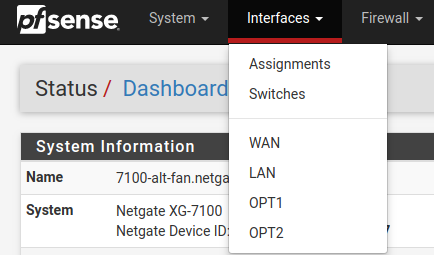
Selecting Switches from the drop-down will bring up the Switch page with four sections:
System
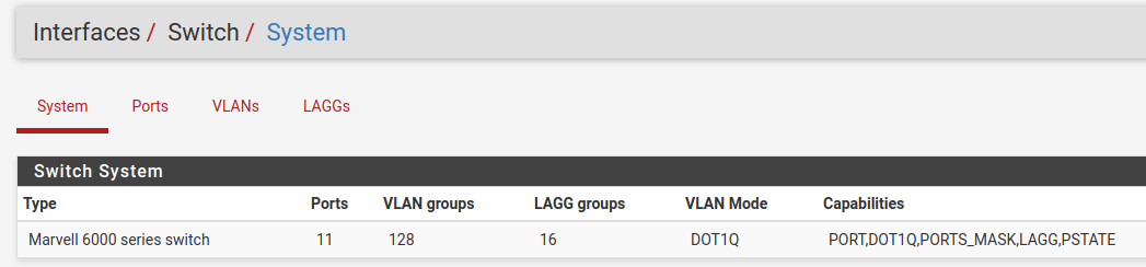
Information on the Marvell 6000 switch
LAGGs
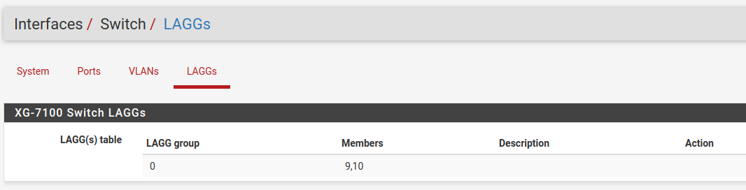
Information on members of the switch LAG
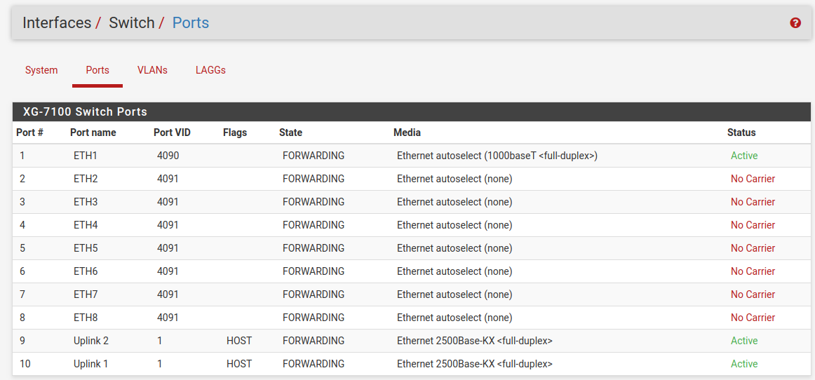
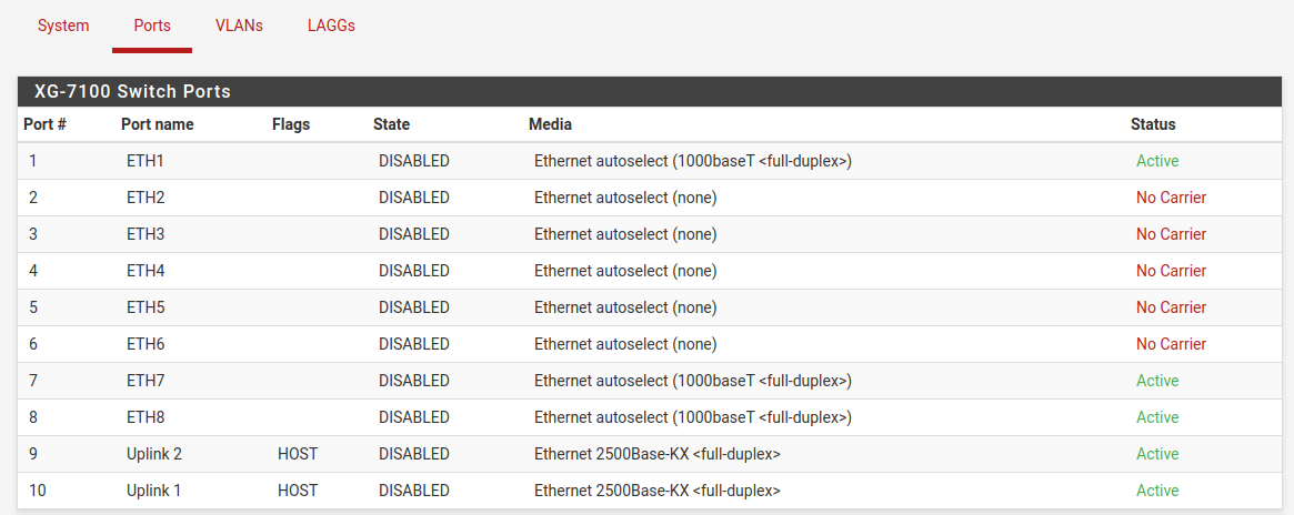
Ports
Information on switchport status and port names. If 802.1q is enabled, this section can also set the native VLAN ID for each port. The switch uses the Port VID as the VLAN ID for inbound untagged traffic on a given port.
802.1q enabled (default)
Port VLAN Mode
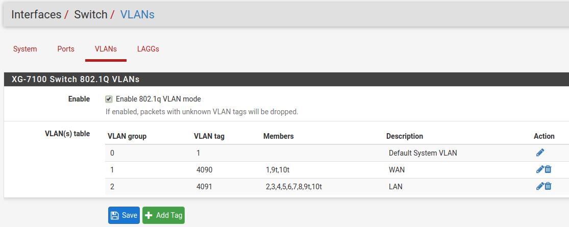
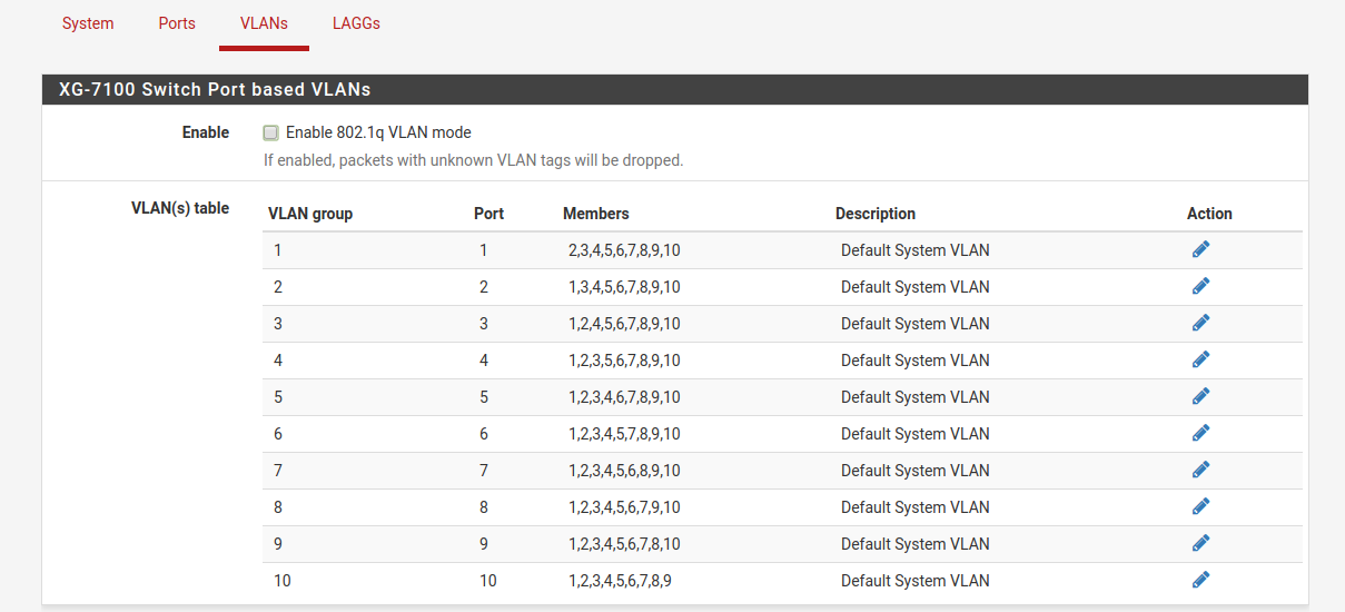
VLANs
Enable/Disable 802.1q VLAN mode. Configure VLAN access/trunk interfaces with 802.1q or configure port groups with Port VLAN Mode.
802.1q enabled (default)
Port VLAN Mode
Interfaces Section
There are also relevant configuration items under Interfaces > Assignments.
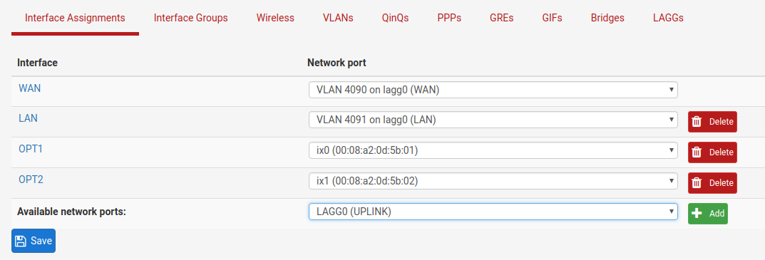
Interface Assignments
Under Interface Assignments, notice LAGG0 (UPLINK) is displayed as an
available port but is not enabled in the list of interfaces. This is because the
default configuration is only expecting VLAN tagged traffic so the VLAN child
interfaces 4090 and 4091 are enabled instead.
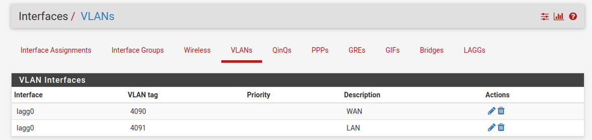
VLANs
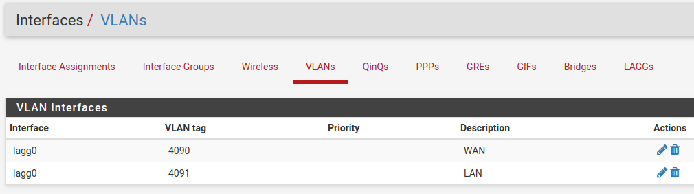
Under VLANs, the list contains the default WAN and LAN VLAN entries.
Additional VLAN networks that used by the switch should be defined here with
lagg0 as the parent interface.
Any additional VLAN interface added to the switch should also be added, enabled, and configured under Interface Assignments. New interfaces also require firewall rules.
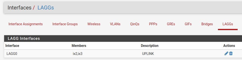
LAGGs
Under LAGGs, the list contains the default lagg0 containing ix2 and ix3.
Danger
Do not modify the lagg0 interface.
Switch Configuration Examples
Dedicated LAN switch
In this scenario, SFP+ port ix0 will be configured as the WAN interface and
ETH1-8 will be configured as a LAN switch.
This example performs the WAN interface reassignment using the console. The WAN assignment can be changed using the GUI.
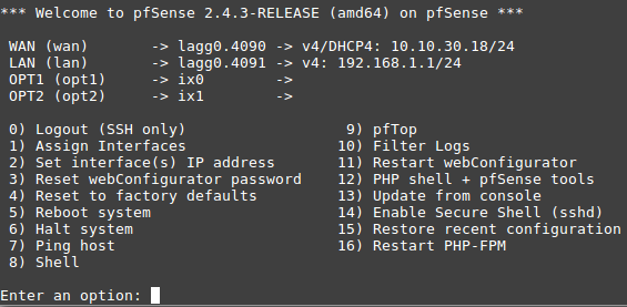
This is what the default interface assignments look like on a Netgate 7100 1U without an addon NIC:
In this example, ix0 is the WAN, so select option 1 to re-assign
WAN from lagg0.4090 to ix0:
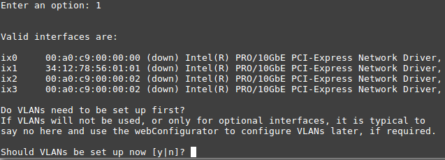
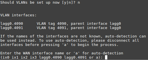
No additional VLANs are needed for this, so enter n to continue.
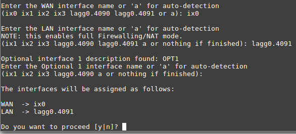
Input ix0 as the new WAN interface name:
Input the same default LAN interface of lagg0.4091 for the LAN
interface name and press Enter to complete the interface reassignment:
The interface assignments should show like this now:
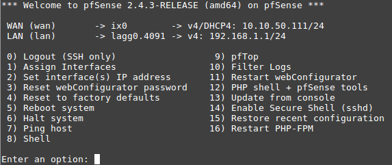
At this point SFP+ port ix0 is now configured as the WAN interface. The LAN
interface is still configured the same as the default. Next, the switch will
need to be updated so that ETH1 (previously WAN) acts the same as ETH2-8. This
will be done from the GUI.
From the GUI, navigate to the Switch VLAN configuration under Interfaces > Switches, VLANs tab:
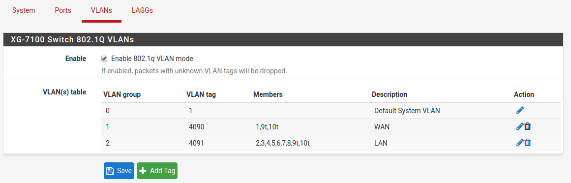
VLAN 4090 is no longer needed since WAN is now dedicated to ix0.
Either select  on the row containing
 4090 to delete this
entry, or click  to remove port
 1 as a member:
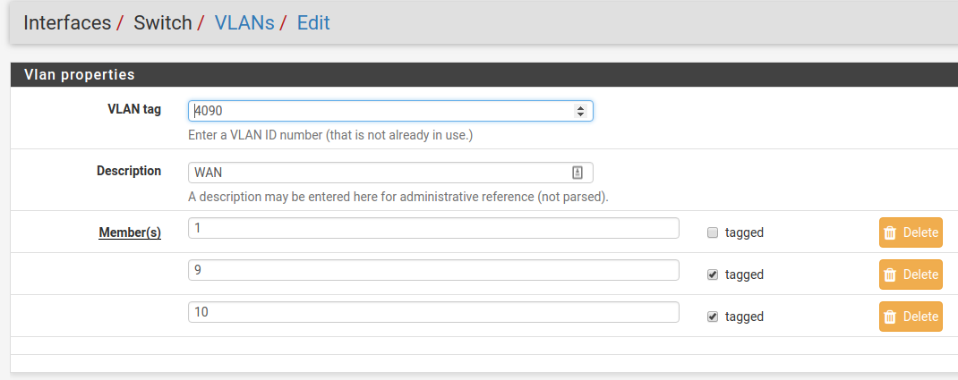
This example removed VLAN 4090 from the switch with .
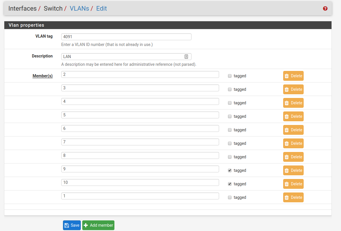
Now edit the VLAN 4091 entry to include Member 1 as shown below:
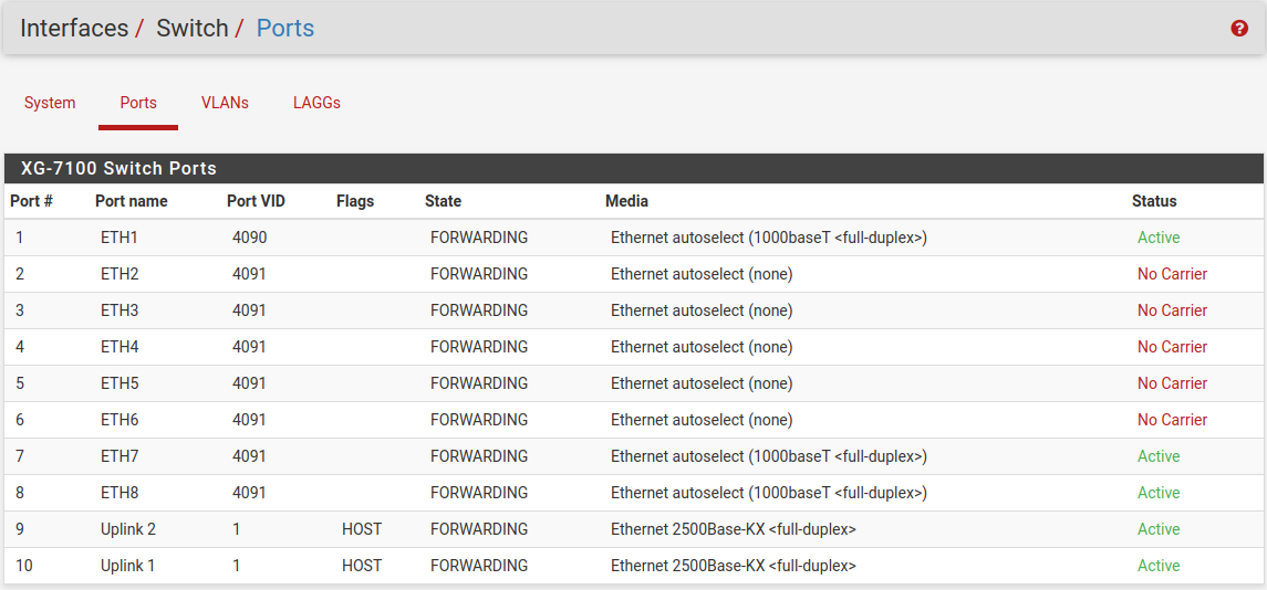
Next, update the Port VID for ETH1 so that it uses VLAN 4091 rather than
the previous VLAN 4090. To do this, click on the Ports tab then click on
the 4090 Port VID to modify it:
Then click on Save:
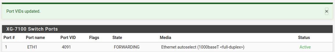
At this point, everything should be configured properly. ETH1-8 will act as a
single LAN switch. One final step that should be performed is to remove the now
unnecessary VLAN 4090 from pfSense® Plus software. So far VLAN 4090 was
only removed from the switch. To remove the unused VLAN, navigate to
Interfaces > Assignments, VLANs tab and use on the
4090 row to remove the VLAN:
Two LAN switches
In this scenario, the LAN switch from the previous example will be split into two LAN switches.
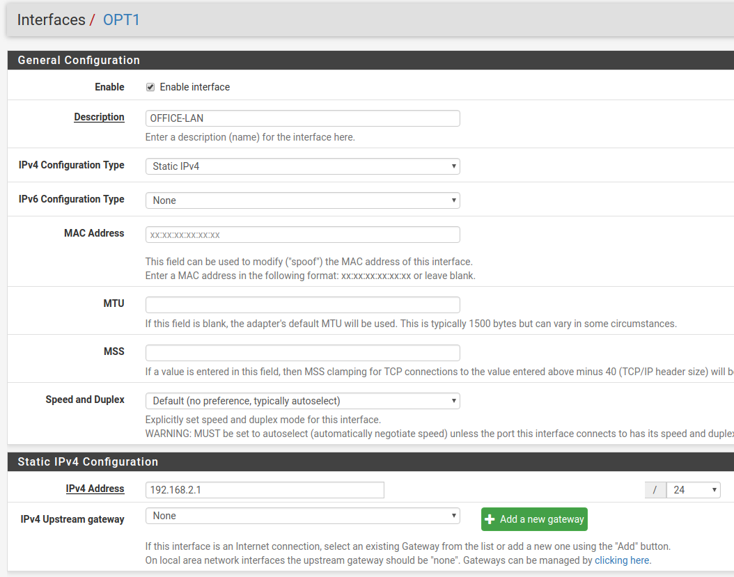
Create a new LAN network in pfSense® Plus software first. Similar to the existing LAN interface, use a separate VLAN interface, so the switch can segment traffic appropriately.
Create a new VLAN with lagg0 as the parent under Interfaces >
Assignments, VLANs tab:
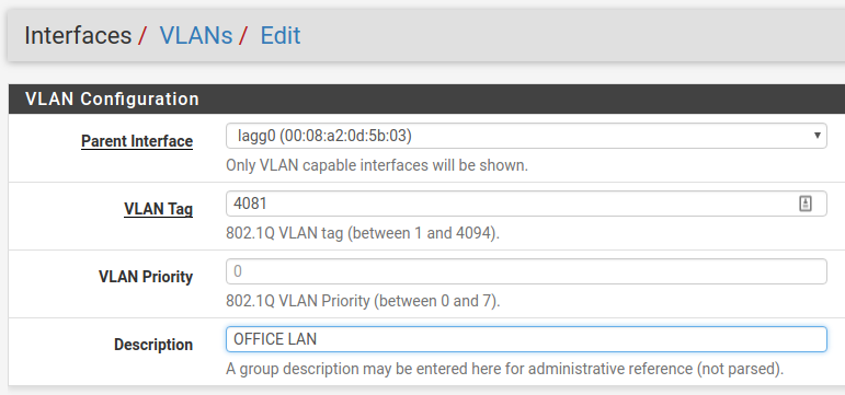
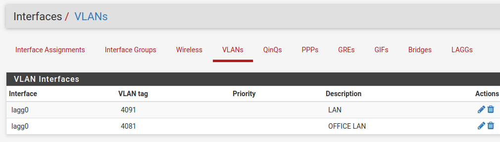
Once the VLAN has been created, it should look something like this:
Add, enable, and configure the VLAN interface under Interfaces Assignments:
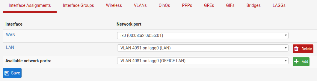
Also create any necessary firewall rules under Firewall > Rules.
Now that pfSense® Plus software knows of this new VLAN network, configure the
switch so that ETH1-4 all use the new network. To do this, go to Interfaces >
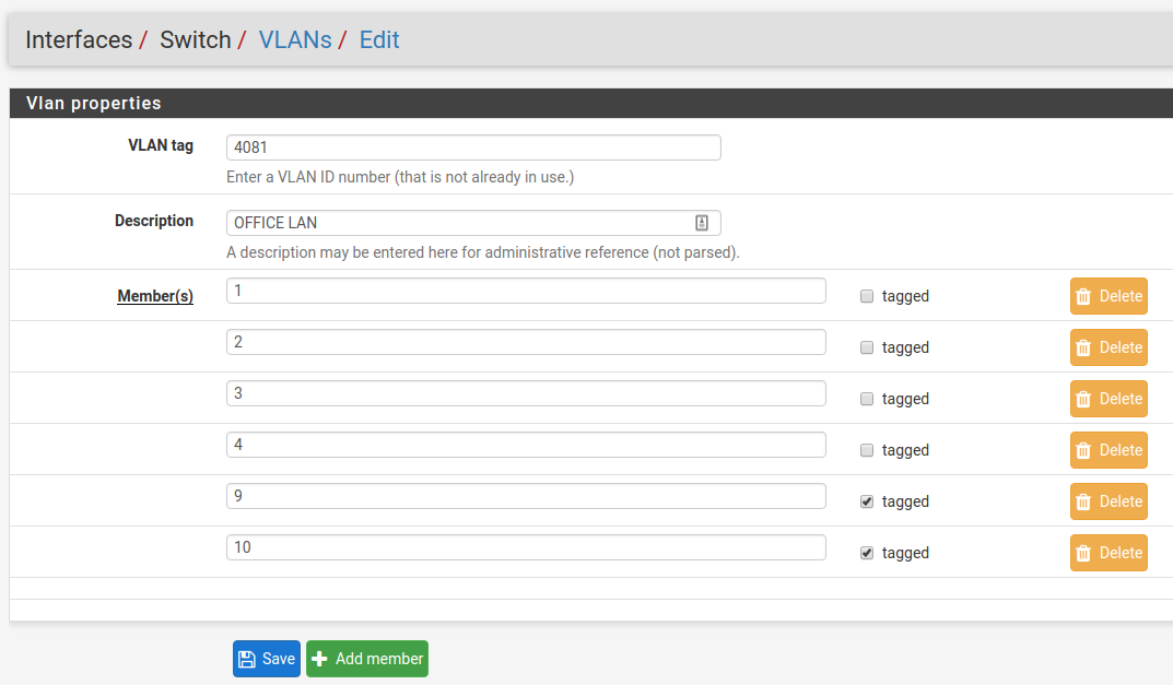
Switches, VLANs tab and click the Add Tag button. Input the VLAN tag
for the new network (same as the VLAN ID configured in the previous steps) and
add ETH1-4 and PORT9-10 (uplinks) as members. Be sure 9 and 10 are
marked as tagged:
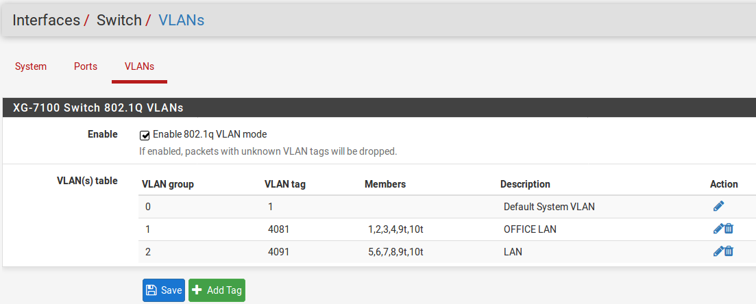
Once this is done, delete the untagged members 1,2,3,4 from VLAN group 2
and click the Save button. The final result should look like this:
Lastly, update the Port VID values to use the new 4081 VLAN rather than
4091 on ETH1-4 and click Save:
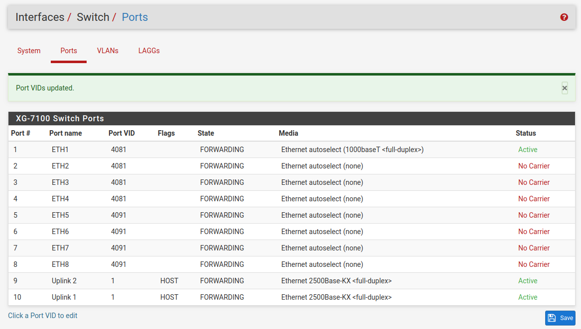
Now ETH1-4 act as a switch for the VLAN 4081 LAN and ETH5-8 act as a switch
for the VLAN 4091 LAN.
Trunking VLAN tagged traffic
Expanding on the previous example, assume there is a management VLAN of 4000
where devices are already tagged on this VLAN prior to reaching the device.
Hosts on this VLAN may come through on ETH8, but there may also be untagged
client traffic.
First, create the management VLAN of 4000 in pfSense® Plus software using
the same steps in the previous example (up to the switch configuration part).
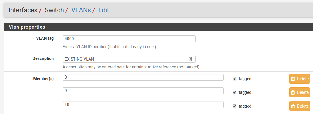
Next, add the VLAN to the switch under Interfaces > Switches, VLANs tab.
ETH8 and PORT9-10 should be added as members and all three will be marked as
tagged:
Once it’s added, the final result should look like this:
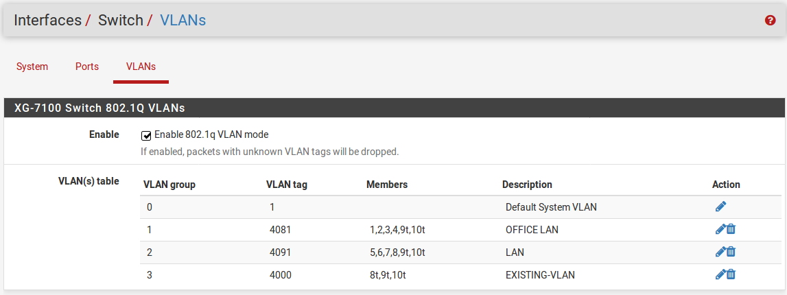
Untagged traffic on ETH8 will be assigned a VLAN ID of 4091. ETH8 and the
uplinks will also accept traffic that has already been tagged with a VLAN ID of
4000 as well.