Input and Output Ports
Front Side
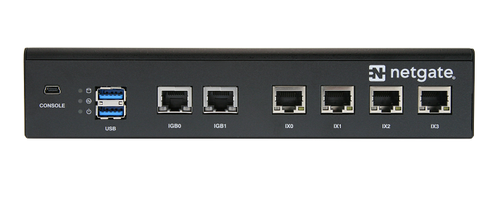
Front view of the Netgate 5100 Firewall Appliance
The items in this image are described by entries in Ethernet Ports and Other Ports and Indicators.
Ethernet Ports
Interface Name |
Port Name |
Port Type |
Port Speed |
|---|---|---|---|
WAN |
IGB0 |
RJ-45 |
1 Gbps |
LAN |
IGB1 |
RJ-45 |
1 Gbps |
IX0 |
RJ-45 |
1 Gbps |
|
IX1 |
RJ-45 |
1 Gbps |
|
IX2 |
RJ-45 |
1 Gbps |
|
IX3 |
RJ-45 |
1 Gbps |
Note
The ix(4) network interfaces on this device do not
implement fixed speed operation. These interfaces emulate a speed/duplex
choice by limiting the values offered during autonegotiation to the
speed/duplex value selected in the GUI.
When connecting different devices to these interfaces the peer should typically be set to autonegotiate, not to a specific speed or duplex value. The exception to this is if the peer interface has the same limitation, in which case both peers should select the same negotiation speed.
Status LED |
State |
Description |
|---|---|---|
Left LED
(Link Status)
|
Solid Amber |
Link has been established and there is no activity on this port |
Blinking Amber |
Link has been established and there is activity on this port |
|
Off |
No link has been established |
|
Right LED
(Speed)
|
Solid Green |
Operating as a 100 Mbps connection |
Blinking Amber |
Operating as a Gigabit connection (1000 Mbps) |
|
Off |
No link has been established |
Note
All Ethernet ports on the Netgate® appliance are compatible with auto-MDI-X and are capable of utilizing either straight-through or crossover Ethernet cables.
Other Ports and Indicators
Status LEDs
2x USB 3.0 Ports
USB Ports
USB ports on the device can be used for a variety of purposes.
The primary use for the USB ports is to install or reinstall the operating system on the device. Beyond that, there are numerous USB devices which can expand the base functionality of the hardware, including some implemented by add-on packages. For example, UPS/Battery Backups, Cellular modems, GPS units, and storage devices. Though the operating system also includes drivers for wired and wireless USB network devices, these are not ideal and should be avoided.
LED Patterns
Status LED |
State |
Description |
|---|---|---|
Top LED |
Blinking Amber |
Add-on storage activity (does not show eMMC activity) |
Middle LED |
Solid Green |
System booted |
Blinking Green |
Software update available |
|
Solid Red |
Halted or in the process of booting |
|
Blinking Red |
Running update process |
|
Blinking Red/Green |
Factory Reset in process |
|
Bottom LED |
Solid Green |
Power |
Rear Side
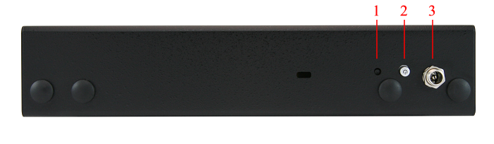
Rear side view of the Netgate 5100 Firewall Appliance
Recessed Reset Button (performs a reset to factory default)
Power Button (powers system on, performs graceful shutdown)
Power
12VDC with threaded locking connector
Power Consumption 7W (idle)

Center Pin Positive
Note
The power button on the SG-5100 has been programmed to perform a graceful shutdown when depressed.
The reset button is only used to reset the system back to factory defaults. It does not respond when pushed while the system is running. See Factory Reset Procedure.