Input and Output Ports
Rear Side
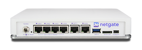
Rear side view of the Netgate 3100 Firewall Appliance
The items in this image are described by entries in Routed Ethernet, Switched Ethernet, and Other Ports.
Routed Ethernet
Interface Name |
Port Name |
Port Type |
|---|---|---|
WAN |
mvneta2 |
RJ-45 |
mvneta0 |
RJ-45 |
LED Pattern |
Description |
|---|---|
Left LED only green |
Flashes with 1Gb traffic, solid with link. |
Both LEDs green |
Both flash with 100Mb traffic, solid with link. |
Right LED only green |
Flashes with 10Mb traffic, solid with link. |
Switched Ethernet
Interface Name |
Port Name |
Port Type |
|---|---|---|
LAN1 |
mvneta1 |
RJ-45 |
LAN2 |
mvneta1 |
RJ-45 |
LAN3 |
mvneta1 |
RJ-45 |
LAN4 |
mvneta1 |
RJ-45 |
The four LAN Ethernet ports are switched ports. By default, all of these ports act as a single switch uplinked to the LAN interface on the firewall.
Note
For more details on how the switch operates, see Switch Overview.
For instructions on how to configure the switch see Configuring the Switch Ports.
LED Pattern |
Description |
|---|---|
Both LEDs green |
Left Flashes with 1 Gb traffic, solid with link. |
Left LED only green |
Left flashes with 100 Mb traffic, solid with link. |
Right LED only green |
Left Flashes with 10 Mb traffic, solid with link. |
Note
Prior to pfSense® software version 2.4.3, the switched Ethernet ports on the SG-3100 did not negotiate auto MDI-X and required crossover cable unless the client-side connection was compatible with auto MDI-X. This was resolved with 2.4.3 and later versions and a crossover cable is no longer required.
Warning
The LAN ports do not implement the Spanning Tree Protocol (STP). Two or more ports connected to another Layer 2 switch, or connected to 2 or more different interconnected switches, could create a flooding loop between the switches. This can cause the router to stop functioning until the loop is resolved.
Other Ports
Power
12VDC 3.33A with threaded locking connector
Power Consumption 5W (idle)
Recessed Reset Button (performs a hard reset, immediately turning the system off)
USB 3.0 Port
Micro SIM
Warning
A hard reset of the system could cause data corruption and should be avoided. Halt or reboot the system through the console menu or the GUI to avoid data corruption.
USB Ports
USB ports on the device can be used for a variety of purposes.
The primary use for the USB ports is to install or reinstall the operating system on the device. Beyond that, there are numerous USB devices which can expand the base functionality of the hardware, including some implemented by add-on packages. For example, UPS/Battery Backups, Cellular modems, GPS units, and storage devices. Though the operating system also includes drivers for wired and wireless USB network devices, these are not ideal and should be avoided.
Front Side
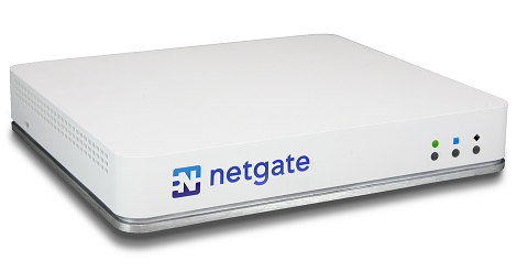
Front view of the Netgate 3100 Firewall Appliance
LED Patterns
Description |
LED Pattern |
|---|---|
Boot in Process |
Circle, then square, then diamond all rapidly flash blue |
Boot Completed/Ready |
Diamond slowly flashes blue |
Upgrade Available |
Square slowly flashes orange |
Upgrade in Progress |
Square slowly flashes orange |